

124
M. Muttakin et al.
R 1 =
1
h w + h r,c2−a
(8.10)
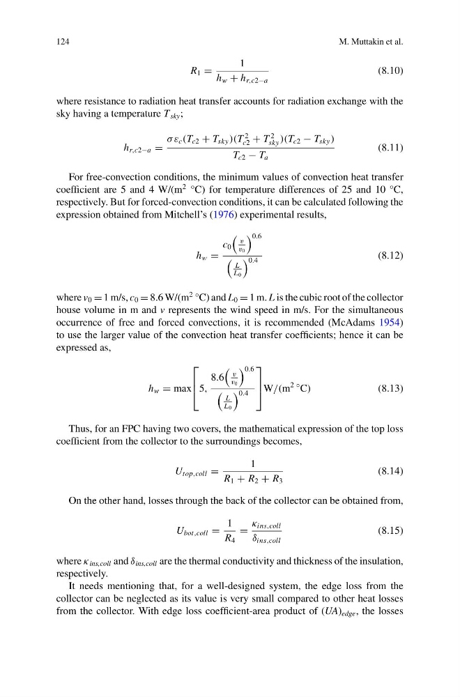
where resistance to radiation heat transfer accounts for radiation exchange with the
sky having a temperature T sky ;
h r,c2−a =
σ ε c (T c2 + T sky )(T
2
c2 + T
2
sky )(T c2 − T sky )
T c2 − T a
(8.11)
For free-convection conditions, the minimum values of convection heat transfer
coefficient are 5 and 4 W/(m
2 °C) for temperature differences of 25 and 10 °C,
respectively. But for forced-convection conditions, it can be calculated following the
expression obtained from Mitchell’s (1976) experimental results,
h w =
c 0
v
v 0
0.6
L
L 0
0.4
(8.12)
where v 0 = 1 m/s, c 0 = 8.6 W/(m
2 °C) and L 0 = 1 m. L is the cubic root of the collector
house volume in m and v represents the wind speed in m/s. For the simultaneous
occurrence of free and forced convections, it is recommended (McAdams 1954)
to use the larger value of the convection heat transfer coefficients; hence it can be
expressed as,
h w = max
⎡
⎢
⎣5,
8.6
v
v 0
0.6
L
L 0
0.4
⎤
⎥
⎦W/(m
2 ◦ C)
(8.13)
Thus, for an FPC having two covers, the mathematical expression of the top loss
coefficient from the collector to the surroundings becomes,
U top,coll =
1
R 1 + R 2 + R 3
(8.14)
On the other hand, losses through the back of the collector can be obtained from,
U bot,coll =
1
R 4
=
κ ins,coll
δ ins,coll
(8.15)
where κ ins,coll and δ ins,coll are the thermal conductivity and thickness of the insulation,
respectively.
It needs mentioning that, for a well-designed system, the edge loss from the
collector can be neglected as its value is very small compared to other heat losses
from the collector. With edge loss coefficient-area product of (UA) edge , the losses
M. Muttakin et al.
R 1 =
1
h w + h r,c2−a
(8.10)
where resistance to radiation heat transfer accounts for radiation exchange with the
sky having a temperature T sky ;
h r,c2−a =
σ ε c (T c2 + T sky )(T
2
c2 + T
2
sky )(T c2 − T sky )
T c2 − T a
(8.11)
For free-convection conditions, the minimum values of convection heat transfer
coefficient are 5 and 4 W/(m
2 °C) for temperature differences of 25 and 10 °C,
respectively. But for forced-convection conditions, it can be calculated following the
expression obtained from Mitchell’s (1976) experimental results,
h w =
c 0
v
v 0
0.6
L
L 0
0.4
(8.12)
where v 0 = 1 m/s, c 0 = 8.6 W/(m
2 °C) and L 0 = 1 m. L is the cubic root of the collector
house volume in m and v represents the wind speed in m/s. For the simultaneous
occurrence of free and forced convections, it is recommended (McAdams 1954)
to use the larger value of the convection heat transfer coefficients; hence it can be
expressed as,
h w = max
⎡
⎢
⎣5,
8.6
v
v 0
0.6
L
L 0
0.4
⎤
⎥
⎦W/(m
2 ◦ C)
(8.13)
Thus, for an FPC having two covers, the mathematical expression of the top loss
coefficient from the collector to the surroundings becomes,
U top,coll =
1
R 1 + R 2 + R 3
(8.14)
On the other hand, losses through the back of the collector can be obtained from,
U bot,coll =
1
R 4
=
κ ins,coll
δ ins,coll
(8.15)
where κ ins,coll and δ ins,coll are the thermal conductivity and thickness of the insulation,
respectively.
It needs mentioning that, for a well-designed system, the edge loss from the
collector can be neglected as its value is very small compared to other heat losses
from the collector. With edge loss coefficient-area product of (UA) edge , the losses