

8 Solar Thermal-Powered Adsorption Chiller
123
G s
Q u
Bottom
Top
Cover 1
Cover 2
Ambient
Ambient
T a
T a
T b
T p
T c1
T c2
1
,
c b a
h −
1
,
r b a
h −
1
1
,
c p c
h −
1
1
,
r p c
h −
1 2
1
,
c c c
h −
1 2
1
,
r c c
h −
2
1
,
r c a
h −
2
1
,
c c a
h −
R 5
R 4
R 3
R 2
R 1
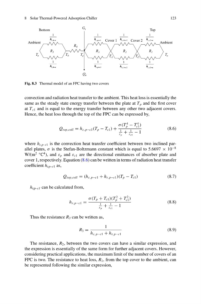
Fig. 8.3 Thermal model of an FPC having two covers
convection and radiation heat transfer to the ambient. This heat loss is essentially the
same as the steady state energy transfer between the plate at T p and the first cover
at T c1 and is equal to the energy transfer between any other two adjacent covers.
Hence, the heat loss through the top of the FPC can be expressed by,
Q top,coll = h c, p−c1 (T p − T c1 ) +
σ (T
4
p − T
4
c1 )
1
ε p
+
1
ε c1
− 1
(8.6)
where h c,p–c1 is the convection heat transfer coefficient between two inclined parallel plates, σ is the Stefan-Boltzmann constant which is equal to 5.6697 × 10
−8
W/(m
2 °C
4 ), and ε p and ε c1 are the directional emittances of absorber plate and
cover 1, respectively. Equation (8.6) can be written in terms of radiation heat transfer
coefficient h r,p–c1 as,
Q top,coll = (h c, p−c1 + h r, p−c1 )(T p − T c1 )
(8.7)
h r,p–c1 can be calculated from,
h r, p−c1 =
σ (T p + T c1 )(T
2
p + T
2
c1 )
1
ε p
+
1
ε c1
− 1
(8.8)
Thus the resistance R 3 can be written as,
R 3 =
1
h c, p−c1 + h r, p−c1
(8.9)
The resistance, R 2 , between the two covers can have a similar expression, and
the expression is essentially of the same form for further adjacent covers. However,
considering practical applications, the maximum limit of the number of covers of an
FPC is two. The resistance to heat loss, R 1 , from the top cover to the ambient, can
be represented following the similar expression,
123
G s
Q u
Bottom
Top
Cover 1
Cover 2
Ambient
Ambient
T a
T a
T b
T p
T c1
T c2
1
,
c b a
h −
1
,
r b a
h −
1
1
,
c p c
h −
1
1
,
r p c
h −
1 2
1
,
c c c
h −
1 2
1
,
r c c
h −
2
1
,
r c a
h −
2
1
,
c c a
h −
R 5
R 4
R 3
R 2
R 1
Fig. 8.3 Thermal model of an FPC having two covers
convection and radiation heat transfer to the ambient. This heat loss is essentially the
same as the steady state energy transfer between the plate at T p and the first cover
at T c1 and is equal to the energy transfer between any other two adjacent covers.
Hence, the heat loss through the top of the FPC can be expressed by,
Q top,coll = h c, p−c1 (T p − T c1 ) +
σ (T
4
p − T
4
c1 )
1
ε p
+
1
ε c1
− 1
(8.6)
where h c,p–c1 is the convection heat transfer coefficient between two inclined parallel plates, σ is the Stefan-Boltzmann constant which is equal to 5.6697 × 10
−8
W/(m
2 °C
4 ), and ε p and ε c1 are the directional emittances of absorber plate and
cover 1, respectively. Equation (8.6) can be written in terms of radiation heat transfer
coefficient h r,p–c1 as,
Q top,coll = (h c, p−c1 + h r, p−c1 )(T p − T c1 )
(8.7)
h r,p–c1 can be calculated from,
h r, p−c1 =
σ (T p + T c1 )(T
2
p + T
2
c1 )
1
ε p
+
1
ε c1
− 1
(8.8)
Thus the resistance R 3 can be written as,
R 3 =
1
h c, p−c1 + h r, p−c1
(8.9)
The resistance, R 2 , between the two covers can have a similar expression, and
the expression is essentially of the same form for further adjacent covers. However,
considering practical applications, the maximum limit of the number of covers of an
FPC is two. The resistance to heat loss, R 1 , from the top cover to the ambient, can
be represented following the similar expression,