

7 Mathematical Modelling of Solar Updraft Tower
99
energy of air at the inlet. Actual efficiency is always less than this limit. Generally,
it lies between 35 and 45%. For this study, the turbine efficiency is taken as 45%.
Two different cases were analysed using the dimensions of the Manzanares plant.
In case 1, the collector efficiency is assumed to be 100%. And in case 2, both convection and radiation losses through the top surface of the greenhouse roof were
accounted and calculated the collector efficiency. The ground is assumed to be a
black body to calculate the tower efficiency.
7.2 Mathematical Modelling of the Power Plant
For this analysis, consider a hypothetical solar updraft tower power plant located in
Ropar, India (Latitude = 30.97° N). Assume the dimensions to be similar to the plant
in Manzanares, Spain (Agarwal et al. 2018). The aim is to calculate the power that
can be extracted using this setup.
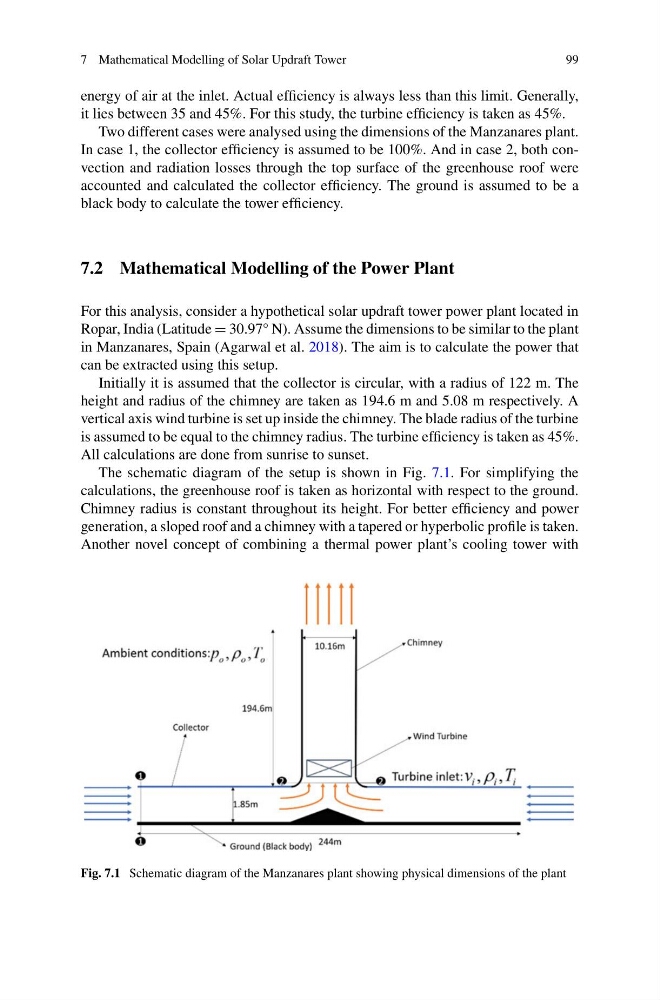
Initially it is assumed that the collector is circular, with a radius of 122 m. The
height and radius of the chimney are taken as 194.6 m and 5.08 m respectively. A
vertical axis wind turbine is set up inside the chimney. The blade radius of the turbine
is assumed to be equal to the chimney radius. The turbine efficiency is taken as 45%.
All calculations are done from sunrise to sunset.
The schematic diagram of the setup is shown in Fig. 7.1. For simplifying the
calculations, the greenhouse roof is taken as horizontal with respect to the ground.
Chimney radius is constant throughout its height. For better efficiency and power
generation, a sloped roof and a chimney with a tapered or hyperbolic profile is taken.
Another novel concept of combining a thermal power plant’s cooling tower with
Fig. 7.1 Schematic diagram of the Manzanares plant showing physical dimensions of the plant
99
energy of air at the inlet. Actual efficiency is always less than this limit. Generally,
it lies between 35 and 45%. For this study, the turbine efficiency is taken as 45%.
Two different cases were analysed using the dimensions of the Manzanares plant.
In case 1, the collector efficiency is assumed to be 100%. And in case 2, both convection and radiation losses through the top surface of the greenhouse roof were
accounted and calculated the collector efficiency. The ground is assumed to be a
black body to calculate the tower efficiency.
7.2 Mathematical Modelling of the Power Plant
For this analysis, consider a hypothetical solar updraft tower power plant located in
Ropar, India (Latitude = 30.97° N). Assume the dimensions to be similar to the plant
in Manzanares, Spain (Agarwal et al. 2018). The aim is to calculate the power that
can be extracted using this setup.
Initially it is assumed that the collector is circular, with a radius of 122 m. The
height and radius of the chimney are taken as 194.6 m and 5.08 m respectively. A
vertical axis wind turbine is set up inside the chimney. The blade radius of the turbine
is assumed to be equal to the chimney radius. The turbine efficiency is taken as 45%.
All calculations are done from sunrise to sunset.
The schematic diagram of the setup is shown in Fig. 7.1. For simplifying the
calculations, the greenhouse roof is taken as horizontal with respect to the ground.
Chimney radius is constant throughout its height. For better efficiency and power
generation, a sloped roof and a chimney with a tapered or hyperbolic profile is taken.
Another novel concept of combining a thermal power plant’s cooling tower with
Fig. 7.1 Schematic diagram of the Manzanares plant showing physical dimensions of the plant