

54
A. Shah
3. The Merten-Andreu-Shah (MAS) equivalent circuit
In his Ph.D. thesis Merten [14], carried out, under the direction of Professor Jordi
Andreu, measurements on amorphous silicon solar cells and modules. These were
mainly so-called “Variable Intensity Measurements (VIM)”, i.e. measurements of
the J-V characteristics for different light intensities [14, 15]. The VIM measurements conducted by Merten led him to a third type of equivalent circuit as shown in
Fig. 3.15c.
Although the equivalent circuit of Fig. 3.15c was derived for amorphous silicon
solar cells—in a recent study [16], Merten and co-workers have shown that it can also
be applied to pn-type solar cells, namely to wafer-based crystalline silicon solar cells.
One may, thus, consider that the MAS Equivalent Circuit as shown in Fig. 3.15c is
universally applicable to different types of solar cells. The MAS Equivalent Circuit
is identical with the Standard Equivalent Circuit, except for the fact that the parallel
resistance R p is now separated into two parts: A “true” shunt resistance R shunt and a
recombination current density sink J rec .
The MAS equivalent circuit is useful for solar cell research, as it correctly
describes the behaviour of the solar cell over many orders of magnitude of illumination levels, i.e. of J ph . It is also useful for the diagnosis of faults in solar cells
and solar modules. It can, however, not be used for analysing and designing the
electric circuit around the solar cell, because J rec is not an element, which can be
used within an electric circuit diagram, as it depends, according to [15], (3.3), on the
internal design and functioning of the solar cell.
3.4.5 Key Parameters of the Solar Cell
1. Short-circuit current density J sc
In short-circuit conditions, R L = 0. The short-circuit current density J sc is, therefore,
for the “ideal” case equivalent to the photo-generated current density source J ph as
shown in Fig. 3.15a–c. In Fig. 3.16 one sees now the maximum value of J sc , which
can be attained for input illumination corresponding to AM 1.5. This maximum value
is obtained when all photons with E ph = hν > E g are usefully absorbed by the solar
cell (where h is Planck’s constant and ν the frequency of light).
2. Open-circuit voltage V oc
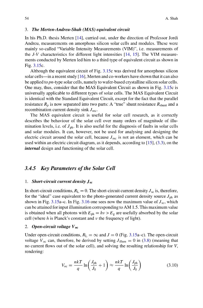
Under open-circuit conditions, R L = ∞ and J = 0 (Fig. 3.15a–c). The open-circuit
voltage V oc can, therefore, be derived by setting J illum = 0 in (3.8) (meaning that
no current flows out of the solar cell), and solving the resulting relationship for V,
rendering:
V oc =
nkT
q
ln
J ph
J 0
+ 1
≈
nkT
q
ln
J ph
J 0
(3.10)
A. Shah
3. The Merten-Andreu-Shah (MAS) equivalent circuit
In his Ph.D. thesis Merten [14], carried out, under the direction of Professor Jordi
Andreu, measurements on amorphous silicon solar cells and modules. These were
mainly so-called “Variable Intensity Measurements (VIM)”, i.e. measurements of
the J-V characteristics for different light intensities [14, 15]. The VIM measurements conducted by Merten led him to a third type of equivalent circuit as shown in
Fig. 3.15c.
Although the equivalent circuit of Fig. 3.15c was derived for amorphous silicon
solar cells—in a recent study [16], Merten and co-workers have shown that it can also
be applied to pn-type solar cells, namely to wafer-based crystalline silicon solar cells.
One may, thus, consider that the MAS Equivalent Circuit as shown in Fig. 3.15c is
universally applicable to different types of solar cells. The MAS Equivalent Circuit
is identical with the Standard Equivalent Circuit, except for the fact that the parallel
resistance R p is now separated into two parts: A “true” shunt resistance R shunt and a
recombination current density sink J rec .
The MAS equivalent circuit is useful for solar cell research, as it correctly
describes the behaviour of the solar cell over many orders of magnitude of illumination levels, i.e. of J ph . It is also useful for the diagnosis of faults in solar cells
and solar modules. It can, however, not be used for analysing and designing the
electric circuit around the solar cell, because J rec is not an element, which can be
used within an electric circuit diagram, as it depends, according to [15], (3.3), on the
internal design and functioning of the solar cell.
3.4.5 Key Parameters of the Solar Cell
1. Short-circuit current density J sc
In short-circuit conditions, R L = 0. The short-circuit current density J sc is, therefore,
for the “ideal” case equivalent to the photo-generated current density source J ph as
shown in Fig. 3.15a–c. In Fig. 3.16 one sees now the maximum value of J sc , which
can be attained for input illumination corresponding to AM 1.5. This maximum value
is obtained when all photons with E ph = hν > E g are usefully absorbed by the solar
cell (where h is Planck’s constant and ν the frequency of light).
2. Open-circuit voltage V oc
Under open-circuit conditions, R L = ∞ and J = 0 (Fig. 3.15a–c). The open-circuit
voltage V oc can, therefore, be derived by setting J illum = 0 in (3.8) (meaning that
no current flows out of the solar cell), and solving the resulting relationship for V,
rendering:
V oc =
nkT
q
ln
J ph
J 0
+ 1
≈
nkT
q
ln
J ph
J 0
(3.10)