

3 Solar Cells: Basics
53
Ideal diode (assumed identical
under dark / illuminated conditions)
Photo-generated
current density source
a
b
c
R
R
J ph
V
series
shunt
J
R L
J rec
Light
D
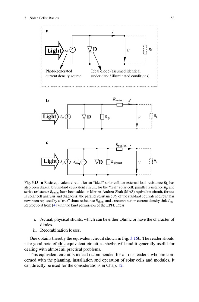
Fig. 3.15 a Basic equivalent circuit, for an “ideal” solar cell; an external load resistance R L has
also been drawn. b Standard equivalent circuit, for the “real” solar cell; parallel resistance R p and
series resistance R series have been added. c Merten-Andreu-Shah (MAS) equivalent circuit, for use
in solar cell analysis and diagnosis; the parallel resistance R p of the standard equivalent circuit has
now been replaced by a “true” shunt resistance R shunt and a recombination current density sink J rec .
Reproduced from [4] with the kind permission of the EPFL Press
i. Actual, physical shunts, which can be either Ohmic or have the character of
diodes.
ii. Recombination losses.
One obtains thereby the equivalent circuit shown in Fig. 3.15b. The reader should
take good note of this equivalent circuit as she/he will find it generally useful for
dealing with almost all practical problems.
This equivalent circuit is indeed recommended for all our readers, who are concerned with the planning, installation and operation of solar cells and modules. It
can directly be used for the considerations in Chap. 12.
53
Ideal diode (assumed identical
under dark / illuminated conditions)
Photo-generated
current density source
a
b
c
R
R
J ph
V
series
shunt
J
R L
J rec
Light
D
Fig. 3.15 a Basic equivalent circuit, for an “ideal” solar cell; an external load resistance R L has
also been drawn. b Standard equivalent circuit, for the “real” solar cell; parallel resistance R p and
series resistance R series have been added. c Merten-Andreu-Shah (MAS) equivalent circuit, for use
in solar cell analysis and diagnosis; the parallel resistance R p of the standard equivalent circuit has
now been replaced by a “true” shunt resistance R shunt and a recombination current density sink J rec .
Reproduced from [4] with the kind permission of the EPFL Press
i. Actual, physical shunts, which can be either Ohmic or have the character of
diodes.
ii. Recombination losses.
One obtains thereby the equivalent circuit shown in Fig. 3.15b. The reader should
take good note of this equivalent circuit as she/he will find it generally useful for
dealing with almost all practical problems.
This equivalent circuit is indeed recommended for all our readers, who are concerned with the planning, installation and operation of solar cells and modules. It
can directly be used for the considerations in Chap. 12.