

134
S. Leu and D. Sontag
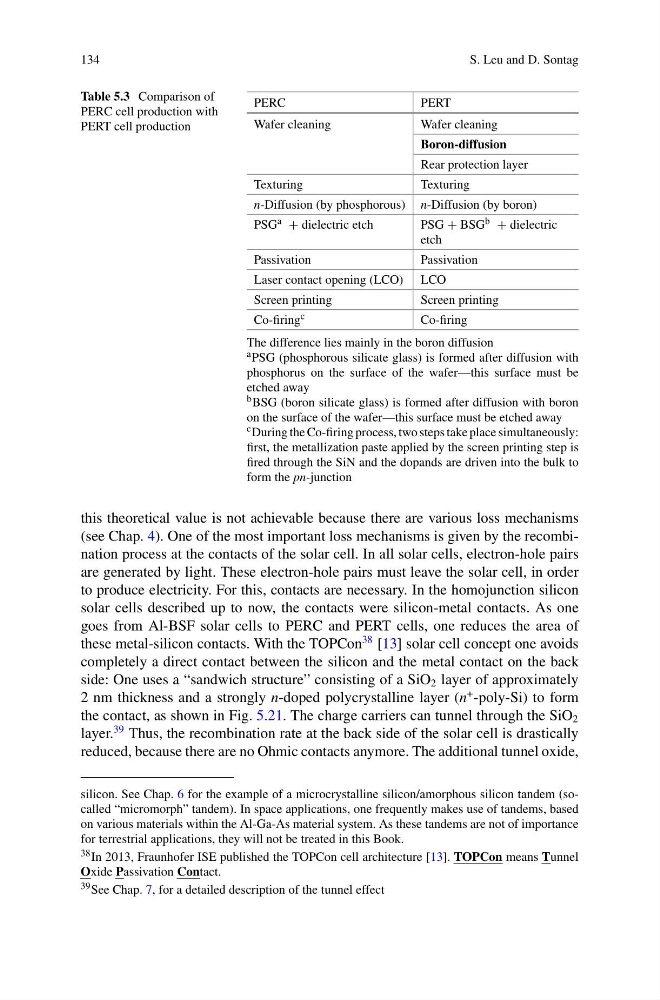
Table 5.3 Comparison of
PERC cell production with
PERT cell production
PERC
PERT
Wafer cleaning
Wafer cleaning
Boron-diffusion
Rear protection layer
Texturing
Texturing
n-Diffusion (by phosphorous) n-Diffusion (by boron)
PSG a + dielectric etch
PSG + BSG b + dielectric
etch
Passivation
Passivation
Laser contact opening (LCO) LCO
Screen printing
Screen printing
Co-firing c
Co-firing
The difference lies mainly in the boron diffusion
a PSG (phosphorous silicate glass) is formed after diffusion with
phosphorus on the surface of the wafer—this surface must be
etched away
b BSG (boron silicate glass) is formed after diffusion with boron
on the surface of the wafer—this surface must be etched away
c During the Co-firing process, two steps take place simultaneously:
first, the metallization paste applied by the screen printing step is
fired through the SiN and the dopands are driven into the bulk to
form the pn-junction
this theoretical value is not achievable because there are various loss mechanisms
(see Chap. 4). One of the most important loss mechanisms is given by the recombination process at the contacts of the solar cell. In all solar cells, electron-hole pairs
are generated by light. These electron-hole pairs must leave the solar cell, in order
to produce electricity. For this, contacts are necessary. In the homojunction silicon
solar cells described up to now, the contacts were silicon-metal contacts. As one
goes from Al-BSF solar cells to PERC and PERT cells, one reduces the area of
these metal-silicon contacts. With the TOPCon
38 [13] solar cell concept one avoids
completely a direct contact between the silicon and the metal contact on the back
side: One uses a “sandwich structure” consisting of a SiO 2 layer of approximately
2 nm thickness and a strongly n-doped polycrystalline layer (n
+ -poly-Si) to form
the contact, as shown in Fig. 5.21. The charge carriers can tunnel through the SiO 2
layer.
39 Thus, the recombination rate at the back side of the solar cell is drastically
reduced, because there are no Ohmic contacts anymore. The additional tunnel oxide,
silicon. See Chap. 6 for the example of a microcrystalline silicon/amorphous silicon tandem (socalled “micromorph” tandem). In space applications, one frequently makes use of tandems, based
on various materials within the Al-Ga-As material system. As these tandems are not of importance
for terrestrial applications, they will not be treated in this Book.
38 In 2013, Fraunhofer ISE published the TOPCon cell architecture [13]. TOPCon means Tunnel
Oxide Passivation Contact.
39 See Chap. 7, for a detailed description of the tunnel effect
S. Leu and D. Sontag
Table 5.3 Comparison of
PERC cell production with
PERT cell production
PERC
PERT
Wafer cleaning
Wafer cleaning
Boron-diffusion
Rear protection layer
Texturing
Texturing
n-Diffusion (by phosphorous) n-Diffusion (by boron)
PSG a + dielectric etch
PSG + BSG b + dielectric
etch
Passivation
Passivation
Laser contact opening (LCO) LCO
Screen printing
Screen printing
Co-firing c
Co-firing
The difference lies mainly in the boron diffusion
a PSG (phosphorous silicate glass) is formed after diffusion with
phosphorus on the surface of the wafer—this surface must be
etched away
b BSG (boron silicate glass) is formed after diffusion with boron
on the surface of the wafer—this surface must be etched away
c During the Co-firing process, two steps take place simultaneously:
first, the metallization paste applied by the screen printing step is
fired through the SiN and the dopands are driven into the bulk to
form the pn-junction
this theoretical value is not achievable because there are various loss mechanisms
(see Chap. 4). One of the most important loss mechanisms is given by the recombination process at the contacts of the solar cell. In all solar cells, electron-hole pairs
are generated by light. These electron-hole pairs must leave the solar cell, in order
to produce electricity. For this, contacts are necessary. In the homojunction silicon
solar cells described up to now, the contacts were silicon-metal contacts. As one
goes from Al-BSF solar cells to PERC and PERT cells, one reduces the area of
these metal-silicon contacts. With the TOPCon
38 [13] solar cell concept one avoids
completely a direct contact between the silicon and the metal contact on the back
side: One uses a “sandwich structure” consisting of a SiO 2 layer of approximately
2 nm thickness and a strongly n-doped polycrystalline layer (n
+ -poly-Si) to form
the contact, as shown in Fig. 5.21. The charge carriers can tunnel through the SiO 2
layer.
39 Thus, the recombination rate at the back side of the solar cell is drastically
reduced, because there are no Ohmic contacts anymore. The additional tunnel oxide,
silicon. See Chap. 6 for the example of a microcrystalline silicon/amorphous silicon tandem (socalled “micromorph” tandem). In space applications, one frequently makes use of tandems, based
on various materials within the Al-Ga-As material system. As these tandems are not of importance
for terrestrial applications, they will not be treated in this Book.
38 In 2013, Fraunhofer ISE published the TOPCon cell architecture [13]. TOPCon means Tunnel
Oxide Passivation Contact.
39 See Chap. 7, for a detailed description of the tunnel effect