

104
S. Leu and D. Sontag
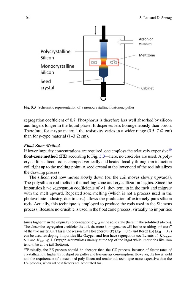
Fig. 5.3 Schematic representation of a monocrystalline float-zone puller
segregation coefficient of 0.7. Phosphorus is therefore less well absorbed by silicon
and lingers longer in the liquid phase. It disperses less homogeneously than boron.
Therefore, for n-type material the resistivity varies in a wider range (0.5–7 cm)
than for p-type material (1–3 cm).
Float-Zone Method
If lower impurity concentrations are required, one employs the relatively expensive
10
float-zone method (FZ) according to Fig. 5.3—here, no crucibles are used. A polycrystalline silicon rod is clamped vertically and heated locally through an induction
coil right up to the melting point. A seed crystal at the lower end of the rod initializes
the drawing process.
The silicon rod now moves slowly down (or: the coil moves slowly upwards).
The polysilicon rod melts in the melting zone and crystallization begins. Since the
impurities have segregation coefficients of <1, they remain in the melt and migrate
with the melt upward. Repeated zone melting (which is not a process used in the
photovoltaic industry, due to cost) allows the production of extremely pure silicon
rods. Actually, this technique is employed to produce the rods used in the Siemens
process. Because no crucible is used in the float zone process, virtually no impurities
times higher than the impurity concentration C solid in the solid state (here: in the solidified silicon).
The closer the segregation coefficient is to 1, the more homogeneous will be the resulting “mixture”
of the two materials. This is the reason that Phosphorous (P) (K P = 0.3) and Boron (B) (K B = 0.7)
can be used for doping. Impurities like Oxygen and Iron have segregation coefficients of: K Oxygen
> 1 and K iron 1. Oxygen accumulates mainly at the top of the ingot while impurities like iron
tend to be at the tail (bottom).
10 Basically, the FZ process should be cheaper than the CZ process, because of faster rates of
crystallization, higher throughput per puller and less energy consumption. However, the lower yield
and the requirement of a machined polysilicon rod render this technique more expensive than the
CZ process, when all cost factors are accounted for.
S. Leu and D. Sontag
Fig. 5.3 Schematic representation of a monocrystalline float-zone puller
segregation coefficient of 0.7. Phosphorus is therefore less well absorbed by silicon
and lingers longer in the liquid phase. It disperses less homogeneously than boron.
Therefore, for n-type material the resistivity varies in a wider range (0.5–7 cm)
than for p-type material (1–3 cm).
Float-Zone Method
If lower impurity concentrations are required, one employs the relatively expensive
10
float-zone method (FZ) according to Fig. 5.3—here, no crucibles are used. A polycrystalline silicon rod is clamped vertically and heated locally through an induction
coil right up to the melting point. A seed crystal at the lower end of the rod initializes
the drawing process.
The silicon rod now moves slowly down (or: the coil moves slowly upwards).
The polysilicon rod melts in the melting zone and crystallization begins. Since the
impurities have segregation coefficients of <1, they remain in the melt and migrate
with the melt upward. Repeated zone melting (which is not a process used in the
photovoltaic industry, due to cost) allows the production of extremely pure silicon
rods. Actually, this technique is employed to produce the rods used in the Siemens
process. Because no crucible is used in the float zone process, virtually no impurities
times higher than the impurity concentration C solid in the solid state (here: in the solidified silicon).
The closer the segregation coefficient is to 1, the more homogeneous will be the resulting “mixture”
of the two materials. This is the reason that Phosphorous (P) (K P = 0.3) and Boron (B) (K B = 0.7)
can be used for doping. Impurities like Oxygen and Iron have segregation coefficients of: K Oxygen
> 1 and K iron 1. Oxygen accumulates mainly at the top of the ingot while impurities like iron
tend to be at the tail (bottom).
10 Basically, the FZ process should be cheaper than the CZ process, because of faster rates of
crystallization, higher throughput per puller and less energy consumption. However, the lower yield
and the requirement of a machined polysilicon rod render this technique more expensive than the
CZ process, when all cost factors are accounted for.