

4 Solar Cells: Optical and Recombination Losses
93
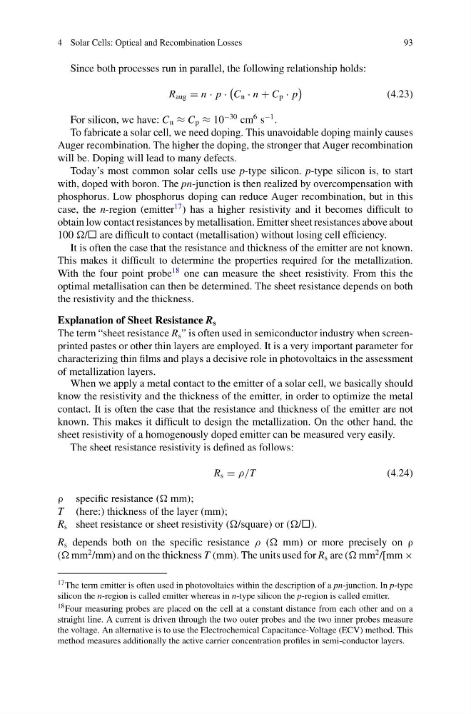
Since both processes run in parallel, the following relationship holds:
R aug = n · p ·
C n · n + C p · p
(4.23)
For silicon, we have: C n ≈ C p ≈ 10
−30 cm
6 s
−1 .
To fabricate a solar cell, we need doping. This unavoidable doping mainly causes
Auger recombination. The higher the doping, the stronger that Auger recombination
will be. Doping will lead to many defects.
Today’s most common solar cells use p-type silicon. p-type silicon is, to start
with, doped with boron. The pn-junction is then realized by overcompensation with
phosphorus. Low phosphorus doping can reduce Auger recombination, but in this
case, the n-region (emitter
17 ) has a higher resistivity and it becomes difficult to
obtain low contact resistances by metallisation. Emitter sheet resistances above about
100 / are difficult to contact (metallisation) without losing cell efficiency.
It is often the case that the resistance and thickness of the emitter are not known.
This makes it difficult to determine the properties required for the metallization.
With the four point probe
18 one can measure the sheet resistivity. From this the
optimal metallisation can then be determined. The sheet resistance depends on both
the resistivity and the thickness.
Explanation of Sheet Resistance R s
The term “sheet resistance R s ” is often used in semiconductor industry when screenprinted pastes or other thin layers are employed. It is a very important parameter for
characterizing thin films and plays a decisive role in photovoltaics in the assessment
of metallization layers.
When we apply a metal contact to the emitter of a solar cell, we basically should
know the resistivity and the thickness of the emitter, in order to optimize the metal
contact. It is often the case that the resistance and thickness of the emitter are not
known. This makes it difficult to design the metallization. On the other hand, the
sheet resistivity of a homogenously doped emitter can be measured very easily.
The sheet resistance resistivity is defined as follows:
R s = ρ/T
(4.24)
ρ specific resistance ( mm);
T (here:) thickness of the layer (mm);
R s sheet resistance or sheet resistivity (/square) or (/).
R s depends both on the specific resistance ρ ( mm) or more precisely on ρ
( mm
2 /mm) and on the thickness T (mm). The units used for R s are ( mm
2 /[mm ×
17 The term emitter is often used in photovoltaics within the description of a pn-junction. In p-type
silicon the n-region is called emitter whereas in n-type silicon the p-region is called emitter.
18 Four measuring probes are placed on the cell at a constant distance from each other and on a
straight line. A current is driven through the two outer probes and the two inner probes measure
the voltage. An alternative is to use the Electrochemical Capacitance-Voltage (ECV) method. This
method measures additionally the active carrier concentration profiles in semi-conductor layers.
93
Since both processes run in parallel, the following relationship holds:
R aug = n · p ·
C n · n + C p · p
(4.23)
For silicon, we have: C n ≈ C p ≈ 10
−30 cm
6 s
−1 .
To fabricate a solar cell, we need doping. This unavoidable doping mainly causes
Auger recombination. The higher the doping, the stronger that Auger recombination
will be. Doping will lead to many defects.
Today’s most common solar cells use p-type silicon. p-type silicon is, to start
with, doped with boron. The pn-junction is then realized by overcompensation with
phosphorus. Low phosphorus doping can reduce Auger recombination, but in this
case, the n-region (emitter
17 ) has a higher resistivity and it becomes difficult to
obtain low contact resistances by metallisation. Emitter sheet resistances above about
100 / are difficult to contact (metallisation) without losing cell efficiency.
It is often the case that the resistance and thickness of the emitter are not known.
This makes it difficult to determine the properties required for the metallization.
With the four point probe
18 one can measure the sheet resistivity. From this the
optimal metallisation can then be determined. The sheet resistance depends on both
the resistivity and the thickness.
Explanation of Sheet Resistance R s
The term “sheet resistance R s ” is often used in semiconductor industry when screenprinted pastes or other thin layers are employed. It is a very important parameter for
characterizing thin films and plays a decisive role in photovoltaics in the assessment
of metallization layers.
When we apply a metal contact to the emitter of a solar cell, we basically should
know the resistivity and the thickness of the emitter, in order to optimize the metal
contact. It is often the case that the resistance and thickness of the emitter are not
known. This makes it difficult to design the metallization. On the other hand, the
sheet resistivity of a homogenously doped emitter can be measured very easily.
The sheet resistance resistivity is defined as follows:
R s = ρ/T
(4.24)
ρ specific resistance ( mm);
T (here:) thickness of the layer (mm);
R s sheet resistance or sheet resistivity (/square) or (/).
R s depends both on the specific resistance ρ ( mm) or more precisely on ρ
( mm
2 /mm) and on the thickness T (mm). The units used for R s are ( mm
2 /[mm ×
17 The term emitter is often used in photovoltaics within the description of a pn-junction. In p-type
silicon the n-region is called emitter whereas in n-type silicon the p-region is called emitter.
18 Four measuring probes are placed on the cell at a constant distance from each other and on a
straight line. A current is driven through the two outer probes and the two inner probes measure
the voltage. An alternative is to use the Electrochemical Capacitance-Voltage (ECV) method. This
method measures additionally the active carrier concentration profiles in semi-conductor layers.