

92
S. Leu and D. Sontag
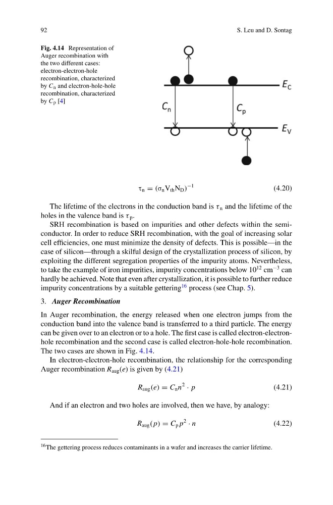
Fig. 4.14 Representation of
Auger recombination with
the two different cases:
electron-electron-hole
recombination, characterized
by C n and electron-hole-hole
recombination, characterized
by C p [4]
τ n = (σ n V th N D )
−1
(4.20)
The lifetime of the electrons in the conduction band is τ n and the lifetime of the
holes in the valence band is τ p .
SRH recombination is based on impurities and other defects within the semiconductor. In order to reduce SRH recombination, with the goal of increasing solar
cell efficiencies, one must minimize the density of defects. This is possible—in the
case of silicon—through a skilful design of the crystallization process of silicon, by
exploiting the different segregation properties of the impurity atoms. Nevertheless,
to take the example of iron impurities, impurity concentrations below 10
12 cm
−3 can
hardly be achieved. Note that even after crystallization, it is possible to further reduce
impurity concentrations by a suitable gettering
16 process (see Chap. 5).
3. Auger Recombination
In Auger recombination, the energy released when one electron jumps from the
conduction band into the valence band is transferred to a third particle. The energy
can be given over to an electron or to a hole. The first case is called electron-electronhole recombination and the second case is called electron-hole-hole recombination.
The two cases are shown in Fig. 4.14.
In electron-electron-hole recombination, the relationship for the corresponding
Auger recombination R aug (e) is given by (4.21)
R aug (e) = C n n
2
· p
(4.21)
And if an electron and two holes are involved, then we have, by analogy:
R aug ( p) = C p p
2
· n
(4.22)
16 The gettering process reduces contaminants in a wafer and increases the carrier lifetime.
S. Leu and D. Sontag
Fig. 4.14 Representation of
Auger recombination with
the two different cases:
electron-electron-hole
recombination, characterized
by C n and electron-hole-hole
recombination, characterized
by C p [4]
τ n = (σ n V th N D )
−1
(4.20)
The lifetime of the electrons in the conduction band is τ n and the lifetime of the
holes in the valence band is τ p .
SRH recombination is based on impurities and other defects within the semiconductor. In order to reduce SRH recombination, with the goal of increasing solar
cell efficiencies, one must minimize the density of defects. This is possible—in the
case of silicon—through a skilful design of the crystallization process of silicon, by
exploiting the different segregation properties of the impurity atoms. Nevertheless,
to take the example of iron impurities, impurity concentrations below 10
12 cm
−3 can
hardly be achieved. Note that even after crystallization, it is possible to further reduce
impurity concentrations by a suitable gettering
16 process (see Chap. 5).
3. Auger Recombination
In Auger recombination, the energy released when one electron jumps from the
conduction band into the valence band is transferred to a third particle. The energy
can be given over to an electron or to a hole. The first case is called electron-electronhole recombination and the second case is called electron-hole-hole recombination.
The two cases are shown in Fig. 4.14.
In electron-electron-hole recombination, the relationship for the corresponding
Auger recombination R aug (e) is given by (4.21)
R aug (e) = C n n
2
· p
(4.21)
And if an electron and two holes are involved, then we have, by analogy:
R aug ( p) = C p p
2
· n
(4.22)
16 The gettering process reduces contaminants in a wafer and increases the carrier lifetime.