

300 m. Thus, this phenomenon was discovered experimentally by authors, for the
first time, and explained by our theoretical analysis for laser diodes. According to
this phenomenon, the change of polarity of the time constant slope of the laser diode
and the slope S f of the function f(I bias ) for OEO on the laser diode may be used for the
correct choice of the laser diode bias currents in OEO and the modulation signal
amplitude, as well as to perform optimization of the modulator structure, the
matching optical unit with the light guide and the temperature-controlled unit.
Figure 8.10a, b shows the amplitude U out functions for OEO oscillation versus the
bias current I bias of the LED emission source for various lengths of the optical fiber:
(a) L ¼ 20 m, and (b) L ¼ 300 m. It can be seen that for various optical fiber lengths,
the plot of these functions has a hysteresis type if the fiber length is more than the
wavelength of RF oscillation.
Time-functions of the OEO generation frequency after power supply switchingon (so-called “frequency stopway”) are measured. These functions are presented in
Fig. 8.10c, d for various light guide lengths (20 and 300 m) and demonstrate the
effect of the oscillation frequency stabilization at optical fiber length growth in
RF FODL.
8.3 OEO on the Powerful Laser for the Phased Microwave
RF FODL for the Active Phased Antenna Array
A goal of this part of our experimental investigations is to study the powerful laser
application for the phase synchronization of fiber-optical channels of the distributed
active phased antenna array system. The laser type is LTI-501, the laser mode is
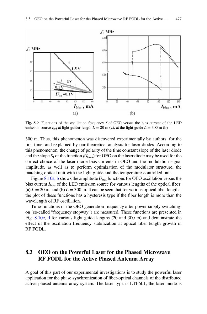
Fig. 8.9 Functions of the oscillation frequency f of OEO versus the bias current of the LED
emission source I led at light guider length L ¼ 20 m (а), at the light guide L ¼ 300 m (b)
8.3 OEO on the Powerful Laser for the Phased Microwave RF FODL for the Active. . .
477
first time, and explained by our theoretical analysis for laser diodes. According to
this phenomenon, the change of polarity of the time constant slope of the laser diode
and the slope S f of the function f(I bias ) for OEO on the laser diode may be used for the
correct choice of the laser diode bias currents in OEO and the modulation signal
amplitude, as well as to perform optimization of the modulator structure, the
matching optical unit with the light guide and the temperature-controlled unit.
Figure 8.10a, b shows the amplitude U out functions for OEO oscillation versus the
bias current I bias of the LED emission source for various lengths of the optical fiber:
(a) L ¼ 20 m, and (b) L ¼ 300 m. It can be seen that for various optical fiber lengths,
the plot of these functions has a hysteresis type if the fiber length is more than the
wavelength of RF oscillation.
Time-functions of the OEO generation frequency after power supply switchingon (so-called “frequency stopway”) are measured. These functions are presented in
Fig. 8.10c, d for various light guide lengths (20 and 300 m) and demonstrate the
effect of the oscillation frequency stabilization at optical fiber length growth in
RF FODL.
8.3 OEO on the Powerful Laser for the Phased Microwave
RF FODL for the Active Phased Antenna Array
A goal of this part of our experimental investigations is to study the powerful laser
application for the phase synchronization of fiber-optical channels of the distributed
active phased antenna array system. The laser type is LTI-501, the laser mode is
Fig. 8.9 Functions of the oscillation frequency f of OEO versus the bias current of the LED
emission source I led at light guider length L ¼ 20 m (а), at the light guide L ¼ 300 m (b)
8.3 OEO on the Powerful Laser for the Phased Microwave RF FODL for the Active. . .
477