

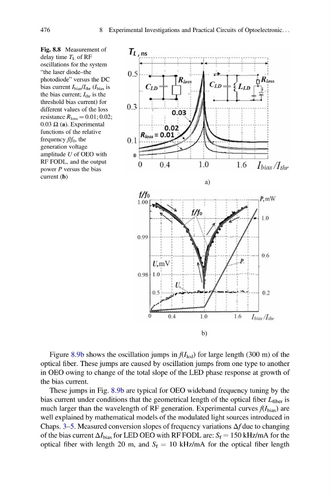
Figure 8.9b shows the oscillation jumps in f(I led ) for large length (300 m) of the
optical fiber. These jumps are caused by oscillation jumps from one type to another
in OEO owing to change of the total slope of the LED phase response at growth of
the bias current.
These jumps in Fig. 8.9b are typical for OEO wideband frequency tuning by the
bias current under conditions that the geometrical length of the optical fiber L fiber is
much larger than the wavelength of RF generation. Experimental curves f(I bias ) are
well explained by mathematical models of the modulated light sources introduced in
Chaps. 3–5. Measured conversion slopes of frequency variations Δf due to changing
of the bias current ΔI bias for LED OEO with RF FODL are: S f ¼ 150 kHz/mA for the
optical fiber with length 20 m, and S f ¼ 10 kHz/mA for the optical fiber length
Fig. 8.8 Measurement of
delay time T L of RF
oscillations for the system
“the laser diode–the
photodiode” versus the DC
bias current I bias /I thr (I bias is
the bias current; I thr is the
threshold bias current) for
different values of the loss
resistance R loss ¼ 0.01; 0.02;
0.03 Ω (а). Experimental
functions of the relative
frequency f/f 0 , the
generation voltage
amplitude U of OEO with
RF FODL, and the output
power P versus the bias
current (b)
476
8 Experimental Investigations and Practical Circuits of Optoelectronic. . .
optical fiber. These jumps are caused by oscillation jumps from one type to another
in OEO owing to change of the total slope of the LED phase response at growth of
the bias current.
These jumps in Fig. 8.9b are typical for OEO wideband frequency tuning by the
bias current under conditions that the geometrical length of the optical fiber L fiber is
much larger than the wavelength of RF generation. Experimental curves f(I bias ) are
well explained by mathematical models of the modulated light sources introduced in
Chaps. 3–5. Measured conversion slopes of frequency variations Δf due to changing
of the bias current ΔI bias for LED OEO with RF FODL are: S f ¼ 150 kHz/mA for the
optical fiber with length 20 m, and S f ¼ 10 kHz/mA for the optical fiber length
Fig. 8.8 Measurement of
delay time T L of RF
oscillations for the system
“the laser diode–the
photodiode” versus the DC
bias current I bias /I thr (I bias is
the bias current; I thr is the
threshold bias current) for
different values of the loss
resistance R loss ¼ 0.01; 0.02;
0.03 Ω (а). Experimental
functions of the relative
frequency f/f 0 , the
generation voltage
amplitude U of OEO with
RF FODL, and the output
power P versus the bias
current (b)
476
8 Experimental Investigations and Practical Circuits of Optoelectronic. . .