

E 2L (t, h, y, x) ¼ |E 2L (h, y, x)| cos [2πν Á t + φ 0L2 (h, y, x) + π/2]. The symmetry
parameter a 0 of the single waveguide, in which the oscillation E 1L (t, h, y, x) propagates, was a 0 > 0, while the second waveguide, in which oscillation E 2L (t, h, y, x)
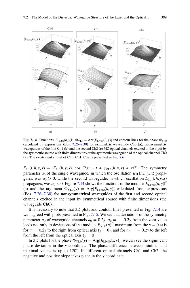
propagates, was a 0 < 0. Figure 7.14 shows the functions of the module |E LN00 (h, y)|
2
(a) and the argument Φ YL0 ( y) ¼ Arg[E LN00 (h, y)] calculated from expressions
(Eqs. 7.26–7.30) for nonsymmetrical waveguides of the first and second optical
channels excited in the input by symmetrical source with finite dimensions (the
waveguide Ch0).
It is necessary to note that 3D plots and contour lines presented in Fig. 7.14 are
well agreed with plots presented in Fig. 7.15. We see that deviations of the symmetry
parameter a 0 of waveguide channels a 0 ¼ 0.2y, a 0 ¼ À 0.2y from the zero value
leads not only to deviations of the module |E YL0 ( y)|
2 maximum from the y ¼ 0 axis
for a 0 ¼ 0.2y to the right from optical axis (y ¼ 0), and for a 0 ¼ À 0.2y to the left
from the left from the optical axis (y ¼ 0).
In 3D plots for the phase Φ YL0 ( y) ¼ Arg[E LN00 (x, y)], we can see the significant
phase deviation in the y coordinate. The phase difference between minimal and
maximal values is up to 120
. In different optical channels Сh1 and Сh2, the
negative and positive slope takes place in the y coordinate.
Fig. 7.14 Functions |E LN00 (h, y)|
2
, Φ YL0 ¼ Arg[E LN00 (h, y)] and contour lines for the phase Φ YL0
calculated by expressions (Eqs. 7.26–7.30) for symmetric waveguide Ch0 (a), nonsymmetric
waveguides of the first Сh1 (b) and the second Ch2 (c) MZ optical channels excited in the input by
the symmetric source with finite dimensions or the symmetric waveguide of the optical channel Ch0
(a). The excitement circuit of Ch0, Ch1, Ch2 is presented in Fig. 7.6
7.2 The Model of the Dielectric Waveguide Structure of the Laser and the Optical. . .
389
parameter a 0 of the single waveguide, in which the oscillation E 1L (t, h, y, x) propagates, was a 0 > 0, while the second waveguide, in which oscillation E 2L (t, h, y, x)
propagates, was a 0 < 0. Figure 7.14 shows the functions of the module |E LN00 (h, y)|
2
(a) and the argument Φ YL0 ( y) ¼ Arg[E LN00 (h, y)] calculated from expressions
(Eqs. 7.26–7.30) for nonsymmetrical waveguides of the first and second optical
channels excited in the input by symmetrical source with finite dimensions (the
waveguide Ch0).
It is necessary to note that 3D plots and contour lines presented in Fig. 7.14 are
well agreed with plots presented in Fig. 7.15. We see that deviations of the symmetry
parameter a 0 of waveguide channels a 0 ¼ 0.2y, a 0 ¼ À 0.2y from the zero value
leads not only to deviations of the module |E YL0 ( y)|
2 maximum from the y ¼ 0 axis
for a 0 ¼ 0.2y to the right from optical axis (y ¼ 0), and for a 0 ¼ À 0.2y to the left
from the left from the optical axis (y ¼ 0).
In 3D plots for the phase Φ YL0 ( y) ¼ Arg[E LN00 (x, y)], we can see the significant
phase deviation in the y coordinate. The phase difference between minimal and
maximal values is up to 120
. In different optical channels Сh1 and Сh2, the
negative and positive slope takes place in the y coordinate.
Fig. 7.14 Functions |E LN00 (h, y)|
2
, Φ YL0 ¼ Arg[E LN00 (h, y)] and contour lines for the phase Φ YL0
calculated by expressions (Eqs. 7.26–7.30) for symmetric waveguide Ch0 (a), nonsymmetric
waveguides of the first Сh1 (b) and the second Ch2 (c) MZ optical channels excited in the input by
the symmetric source with finite dimensions or the symmetric waveguide of the optical channel Ch0
(a). The excitement circuit of Ch0, Ch1, Ch2 is presented in Fig. 7.6
7.2 The Model of the Dielectric Waveguide Structure of the Laser and the Optical. . .
389