

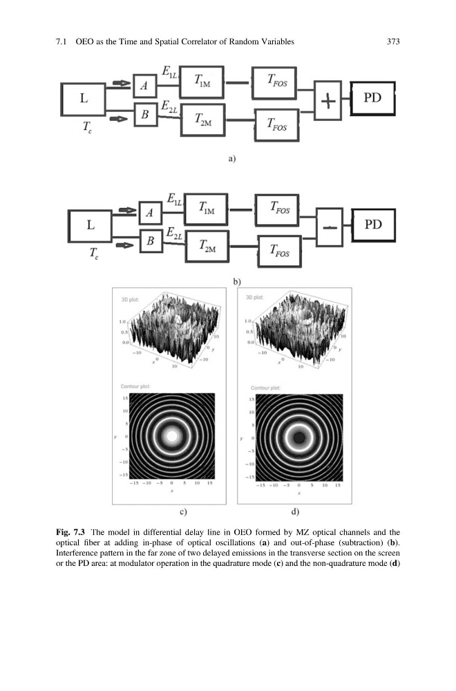
Fig. 7.3 The model in differential delay line in OEO formed by MZ optical channels and the
optical fiber at adding in-phase of optical oscillations (a) and out-of-phase (subtraction) (b).
Interference pattern in the far zone of two delayed emissions in the transverse section on the screen
or the PD area: at modulator operation in the quadrature mode (c) and the non-quadrature mode (d)
7.1 OEO as the Time and Spatial Correlator of Random Variables
373
optical fiber at adding in-phase of optical oscillations (a) and out-of-phase (subtraction) (b).
Interference pattern in the far zone of two delayed emissions in the transverse section on the screen
or the PD area: at modulator operation in the quadrature mode (c) and the non-quadrature mode (d)
7.1 OEO as the Time and Spatial Correlator of Random Variables
373