

spectrum in the PD input will have the maximal value. Accordingly, noises introduced by the DC component will be maximal in the PD load.
Since the problem of noises caused by the DC component had discussed in
Chap. 3, here we pay attention to the circumstance that due to the spatial
nonuniformity (in transverse section) of MZ waveguide optical channels, in order
to achieve of DC suppression to values, for example, less than 10
À5 is technically the
difficult enough task. This is caused by the fact that the laser wavelength is close to
the overall dimensions of the waveguide, and the nonuniformity of optical channels
in MZ causes the significant phase deviations of the wave in the transverse section
during its propagation. It is easy to make sure that PSD in the PD input and the
suppression degree of DC component will also depend on the excitation coefficients
of optical channels А and В.
Figure 7.3 presents the model of the differential delay line in OEO, which is
formed by optical channels of the MZ modulator and the optical fiber at optical
oscillations adding in-phase (a) and out-of-phase (or at subtraction) (b). The interference pattern (3D and the contour plot) in the far zone (on PD area) of two delayed
optical oscillations in the transverse section on the screen of the PD area are shown in
Fig. 7.3c, d: at modulator operation in the quadrature mode (or at relative phase
difference of 90
) (с) and in the non-quadrature mode (or at the relative phase
difference of 180
) (d).
Let us illustrate the influence of excitation coefficients A and B of the first and
second MZ optical channels upon PSD S ηPD ( f ) for structures in Fig. 7.3a, b. Now
we write ACF in the PD input as the formula (taking into account A and B):
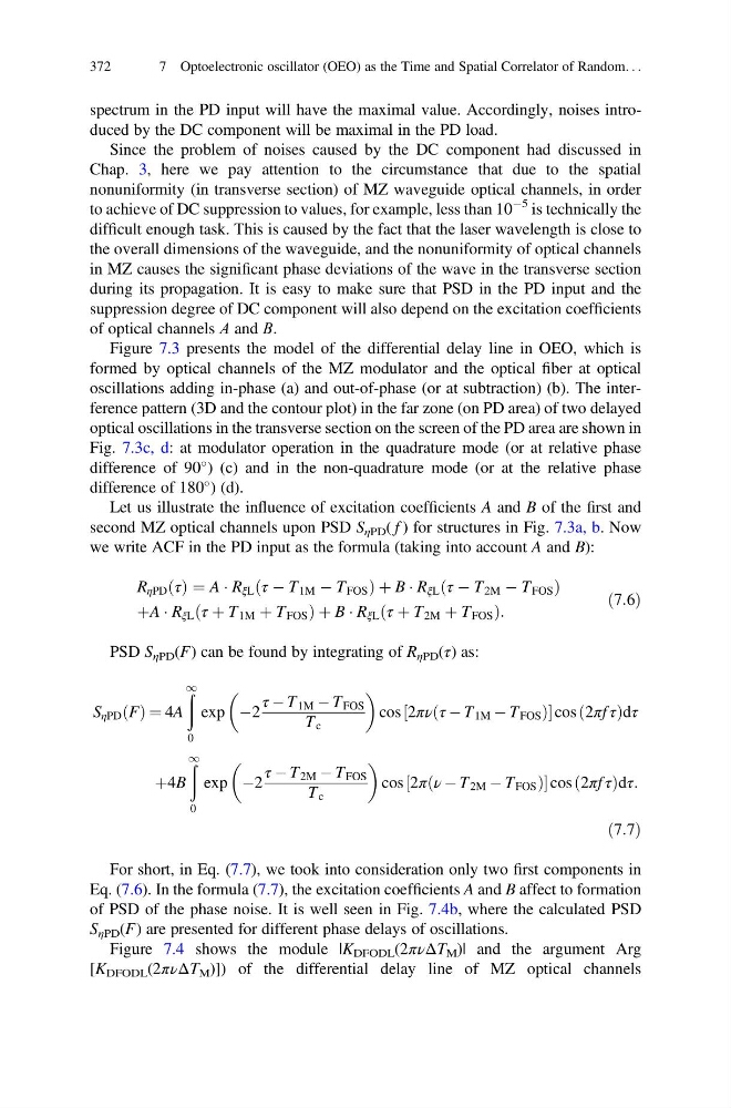
R ηPD τ
ð Þ ¼ A Á R ξL τ À T 1M À T FOS
ð
Þ þ B Á R ξL τ À T 2M À T FOS
ð
Þ
þA Á R ξL τ þ T 1M þ T FOS
ð
Þ þ B Á R ξL τ þ T 2M þ T FOS
ð
Þ :
ð7:6Þ
PSD S ηPD (F) can be found by integrating of R ηPD (τ) as:
S ηPD F
ð Þ ¼ 4A
ð
1
0
exp À2
τ À T 1M À T FOS
T c
cos 2πν τ À T 1M À T FOS
ð
Þ
½
cos 2πf τ
ð
Þdτ
þ4B
ð
1
0
exp À2
τ À T 2M À T FOS
T c
cos 2π ν À T 2M À T FOS
ð
Þ
½
cos 2πf τ
ð
Þdτ:
ð7:7Þ
For short, in Eq. (7.7), we took into consideration only two first components in
Eq. (7.6). In the formula (7.7), the excitation coefficients A and B affect to formation
of PSD of the phase noise. It is well seen in Fig. 7.4b, where the calculated PSD
S ηPD (F) are presented for different phase delays of oscillations.
Figure 7.4 shows the module |K DFODL (2πνΔT M )| and the argument Arg
[K DFODL (2πνΔT M )]) of the differential delay line of MZ optical channels
372
7 Optoelectronic oscillator (OEO) as the Time and Spatial Correlator of Random. . .
Since the problem of noises caused by the DC component had discussed in
Chap. 3, here we pay attention to the circumstance that due to the spatial
nonuniformity (in transverse section) of MZ waveguide optical channels, in order
to achieve of DC suppression to values, for example, less than 10
À5 is technically the
difficult enough task. This is caused by the fact that the laser wavelength is close to
the overall dimensions of the waveguide, and the nonuniformity of optical channels
in MZ causes the significant phase deviations of the wave in the transverse section
during its propagation. It is easy to make sure that PSD in the PD input and the
suppression degree of DC component will also depend on the excitation coefficients
of optical channels А and В.
Figure 7.3 presents the model of the differential delay line in OEO, which is
formed by optical channels of the MZ modulator and the optical fiber at optical
oscillations adding in-phase (a) and out-of-phase (or at subtraction) (b). The interference pattern (3D and the contour plot) in the far zone (on PD area) of two delayed
optical oscillations in the transverse section on the screen of the PD area are shown in
Fig. 7.3c, d: at modulator operation in the quadrature mode (or at relative phase
difference of 90
) (с) and in the non-quadrature mode (or at the relative phase
difference of 180
) (d).
Let us illustrate the influence of excitation coefficients A and B of the first and
second MZ optical channels upon PSD S ηPD ( f ) for structures in Fig. 7.3a, b. Now
we write ACF in the PD input as the formula (taking into account A and B):
R ηPD τ
ð Þ ¼ A Á R ξL τ À T 1M À T FOS
ð
Þ þ B Á R ξL τ À T 2M À T FOS
ð
Þ
þA Á R ξL τ þ T 1M þ T FOS
ð
Þ þ B Á R ξL τ þ T 2M þ T FOS
ð
Þ :
ð7:6Þ
PSD S ηPD (F) can be found by integrating of R ηPD (τ) as:
S ηPD F
ð Þ ¼ 4A
ð
1
0
exp À2
τ À T 1M À T FOS
T c
cos 2πν τ À T 1M À T FOS
ð
Þ
½
cos 2πf τ
ð
Þdτ
þ4B
ð
1
0
exp À2
τ À T 2M À T FOS
T c
cos 2π ν À T 2M À T FOS
ð
Þ
½
cos 2πf τ
ð
Þdτ:
ð7:7Þ
For short, in Eq. (7.7), we took into consideration only two first components in
Eq. (7.6). In the formula (7.7), the excitation coefficients A and B affect to formation
of PSD of the phase noise. It is well seen in Fig. 7.4b, where the calculated PSD
S ηPD (F) are presented for different phase delays of oscillations.
Figure 7.4 shows the module |K DFODL (2πνΔT M )| and the argument Arg
[K DFODL (2πνΔT M )]) of the differential delay line of MZ optical channels
372
7 Optoelectronic oscillator (OEO) as the Time and Spatial Correlator of Random. . .