

In OC2, the emission E 2L is modulated by the input RF signal of the voltage
u ¼ u RF (t) on the optical phase, and the time delay of the optical oscillation in the
OC2 output with the regard to the MZ input is T 2M ¼ T 2M [u(t)]. In the OC1 output,
the time delay remains constant and equal to T 1M . Then, optical emissions from
outputs of the first OC1 E 1L and the second OC2 E 2L optical channels, owing to the
second output Х-coupler, pass to the FOS input, in which they are delayed by the
time T FOS and then are applied to the photodetector PD.
6.2.1 Influence of the Phase Noise PSD on the Irregularity
of MZ Optical Channels and the Spatial Laser
Coherence
Presented photo-pictures (Fig. 6.6) of distribution variations of the optical emission
intensities in the optical channels OC1 and OC2 in the MZ modulator of the
microwave range are rather informative. From the analysis of intensity distribution,
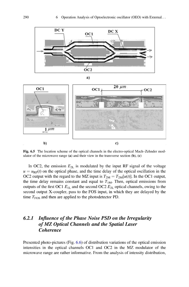
Fig. 6.5 The location scheme of the optical channels in the electro-optical Mach–Zehnder modulator of the microwave range (a) and their view in the transverse section (b), (c)
290
6 Operation Analysis of Optoelectronic oscillator (OEO) with External. . .
u ¼ u RF (t) on the optical phase, and the time delay of the optical oscillation in the
OC2 output with the regard to the MZ input is T 2M ¼ T 2M [u(t)]. In the OC1 output,
the time delay remains constant and equal to T 1M . Then, optical emissions from
outputs of the first OC1 E 1L and the second OC2 E 2L optical channels, owing to the
second output Х-coupler, pass to the FOS input, in which they are delayed by the
time T FOS and then are applied to the photodetector PD.
6.2.1 Influence of the Phase Noise PSD on the Irregularity
of MZ Optical Channels and the Spatial Laser
Coherence
Presented photo-pictures (Fig. 6.6) of distribution variations of the optical emission
intensities in the optical channels OC1 and OC2 in the MZ modulator of the
microwave range are rather informative. From the analysis of intensity distribution,
Fig. 6.5 The location scheme of the optical channels in the electro-optical Mach–Zehnder modulator of the microwave range (a) and their view in the transverse section (b), (c)
290
6 Operation Analysis of Optoelectronic oscillator (OEO) with External. . .