

u RF t
ð Þ ¼ U 0 cos 2π f 0 t þ ϕ 0e
ð
Þ ,
ð6:1Þ
where U 0 ¼ U 0M ¼ U 0F is the oscillation amplitude in the MZ modulator input or in
the filter output, f 0 is the oscillation radio frequency, ϕ 0e is the constant phase shift.
We should note that if the laser spectrum width Δv L is much less than the radio
frequency f 0 of the subcarrier Δv L ( f 0 , the modulated emission is formed in the
modulator output in the small-signal mode. This optical emission represents the sum
of three coherent components in the spectrum, which frequencies are, relatively,
ν 1 ¼ ν 0 À f 0 , ν 2 ¼ ν 0 , ν 3 ¼ ν 0 + f 0 . Two of these optical frequencies v 1 and v 3 are
separated from the central laser optical frequency v 0 by the subcarrier frequency f 0 .
In the further description, we examine OEO with the MZ modulator, in which the
laser is the high-coherent source of the optical emission and Δv L ( f 0 , and the
optical Mach–Zehnder modulator is the modulator in OEO.
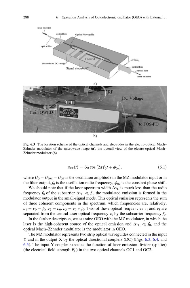
The MZ modulator represents two strip optical waveguides connected in the input
Y and in the output Х by the optical directional couplers (DC) (Figs. 6.3, 6.4, and
6.5). The input Y-coupler executes the function of laser emission divider (splitter)
(the electrical field strength E L ) in the two optical channels OC1 and OC2.
Fig. 6.3 The location scheme of the optical channels and electrodes in the electro-optical Mach–
Zehnder modulator of the microwave range (a), the overall view of the electro-optical Mach–
Zehnder modulator (b)
288
6 Operation Analysis of Optoelectronic oscillator (OEO) with External. . .
ð Þ ¼ U 0 cos 2π f 0 t þ ϕ 0e
ð
Þ ,
ð6:1Þ
where U 0 ¼ U 0M ¼ U 0F is the oscillation amplitude in the MZ modulator input or in
the filter output, f 0 is the oscillation radio frequency, ϕ 0e is the constant phase shift.
We should note that if the laser spectrum width Δv L is much less than the radio
frequency f 0 of the subcarrier Δv L ( f 0 , the modulated emission is formed in the
modulator output in the small-signal mode. This optical emission represents the sum
of three coherent components in the spectrum, which frequencies are, relatively,
ν 1 ¼ ν 0 À f 0 , ν 2 ¼ ν 0 , ν 3 ¼ ν 0 + f 0 . Two of these optical frequencies v 1 and v 3 are
separated from the central laser optical frequency v 0 by the subcarrier frequency f 0 .
In the further description, we examine OEO with the MZ modulator, in which the
laser is the high-coherent source of the optical emission and Δv L ( f 0 , and the
optical Mach–Zehnder modulator is the modulator in OEO.
The MZ modulator represents two strip optical waveguides connected in the input
Y and in the output Х by the optical directional couplers (DC) (Figs. 6.3, 6.4, and
6.5). The input Y-coupler executes the function of laser emission divider (splitter)
(the electrical field strength E L ) in the two optical channels OC1 and OC2.
Fig. 6.3 The location scheme of the optical channels and electrodes in the electro-optical Mach–
Zehnder modulator of the microwave range (a), the overall view of the electro-optical Mach–
Zehnder modulator (b)
288
6 Operation Analysis of Optoelectronic oscillator (OEO) with External. . .