

Topics in Current Chemistry (2018) 376:44
1 3
the small characteristic dimensions in microreactors, the high effective interfacial area
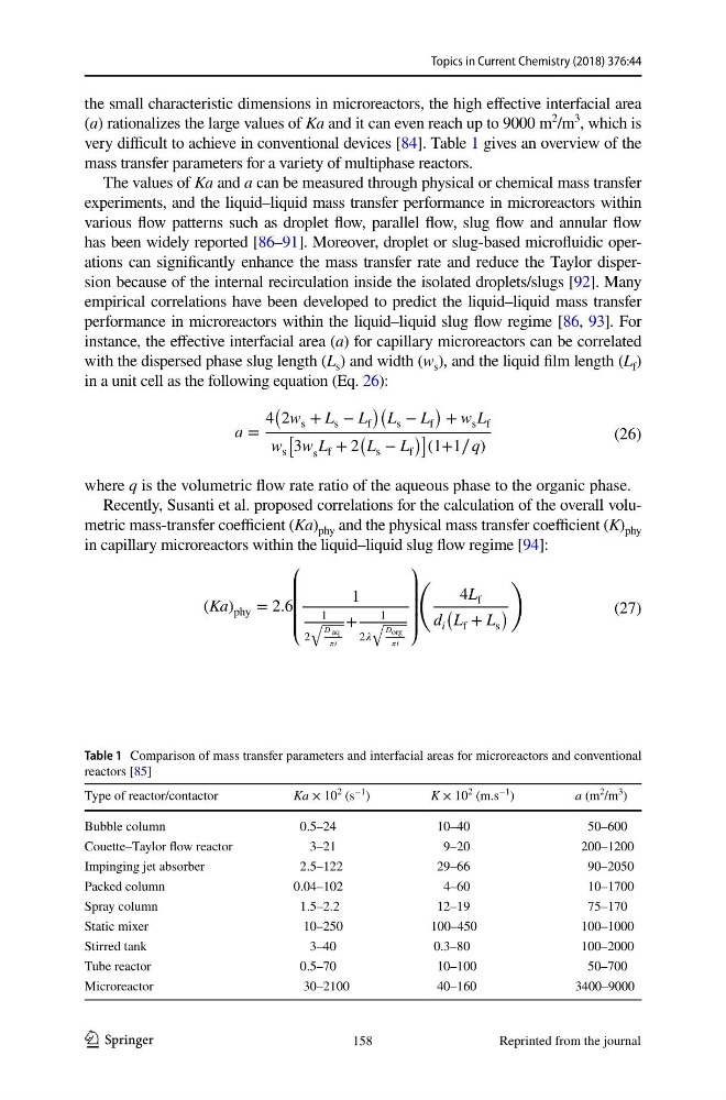
(a) rationalizes the large values of Ka and it can even reach up to 9000 m
2
/m
3
, which is
very difficult to achieve in conventional devices [84]. Table 1 gives an overview of the
mass transfer parameters for a variety of multiphase reactors.
The values of Ka and a can be measured through physical or chemical mass transfer
experiments, and the liquid–liquid mass transfer performance in microreactors within
various flow patterns such as droplet flow, parallel flow, slug flow and annular flow
has been widely reported [86–91]. Moreover, droplet or slug-based microfluidic operations can significantly enhance the mass transfer rate and reduce the Taylor dispersion because of the internal recirculation inside the isolated droplets/slugs [92]. Many
empirical correlations have been developed to predict the liquid–liquid mass transfer
performance in microreactors within the liquid–liquid slug flow regime [86, 93]. For
instance, the effective interfacial area (a) for capillary microreactors can be correlated
with the dispersed phase slug length (L s ) and width (w s ), and the liquid film length (L f )
in a unit cell as the following equation (Eq. 26):
where q is the volumetric flow rate ratio of the aqueous phase to the organic phase.
Recently, Susanti et al. proposed correlations for the calculation of the overall volumetric mass-transfer coefficient (Ka) phy and the physical mass transfer coefficient (K) phy
in capillary microreactors within the liquid–liquid slug flow regime [94]:
(26)
a =
4
2w s + L s − L f
L s − L f
+ w s L f
w s
3w s L f + 2
L s − L f
(1+1∕ q)
(27)
(Ka) phy = 2.6
⎛
⎜
⎜
⎜
⎝
1
1
2
�
D aq
t
+
1
2
�
D org
t
⎞
⎟
⎟
⎟
⎠
�
4L f
d i
�
L f + L s
�
�
Table 1 Comparison of mass transfer parameters and interfacial areas for microreactors and conventional
reactors [85]
Type of reactor/contactor
Ka × 10
2 (s
−1
)
K × 10
2 (m.s
−1 )
a (m
2
/m
3 )
Bubble column
0.5–24
10–40
50–600
Couette–Taylor flow reactor
3–21
9–20
200–1200
Impinging jet absorber
2.5–122
29–66
90–2050
Packed column
0.04–102
4–60
10–1700
Spray column
1.5–2.2
12–19
75–170
Static mixer
10–250
100–450
100–1000
Stirred tank
3–40
0.3–80
100–2000
Tube reactor
0.5–70
10–100
50–700
Microreactor
30–2100
40–160
3400–9000
158
Reprinted from the journal
1 3
the small characteristic dimensions in microreactors, the high effective interfacial area
(a) rationalizes the large values of Ka and it can even reach up to 9000 m
2
/m
3
, which is
very difficult to achieve in conventional devices [84]. Table 1 gives an overview of the
mass transfer parameters for a variety of multiphase reactors.
The values of Ka and a can be measured through physical or chemical mass transfer
experiments, and the liquid–liquid mass transfer performance in microreactors within
various flow patterns such as droplet flow, parallel flow, slug flow and annular flow
has been widely reported [86–91]. Moreover, droplet or slug-based microfluidic operations can significantly enhance the mass transfer rate and reduce the Taylor dispersion because of the internal recirculation inside the isolated droplets/slugs [92]. Many
empirical correlations have been developed to predict the liquid–liquid mass transfer
performance in microreactors within the liquid–liquid slug flow regime [86, 93]. For
instance, the effective interfacial area (a) for capillary microreactors can be correlated
with the dispersed phase slug length (L s ) and width (w s ), and the liquid film length (L f )
in a unit cell as the following equation (Eq. 26):
where q is the volumetric flow rate ratio of the aqueous phase to the organic phase.
Recently, Susanti et al. proposed correlations for the calculation of the overall volumetric mass-transfer coefficient (Ka) phy and the physical mass transfer coefficient (K) phy
in capillary microreactors within the liquid–liquid slug flow regime [94]:
(26)
a =
4
2w s + L s − L f
L s − L f
+ w s L f
w s
3w s L f + 2
L s − L f
(1+1∕ q)
(27)
(Ka) phy = 2.6
⎛
⎜
⎜
⎜
⎝
1
1
2
�
D aq
t
+
1
2
�
D org
t
⎞
⎟
⎟
⎟
⎠
�
4L f
d i
�
L f + L s
�
�
Table 1 Comparison of mass transfer parameters and interfacial areas for microreactors and conventional
reactors [85]
Type of reactor/contactor
Ka × 10
2 (s
−1
)
K × 10
2 (m.s
−1 )
a (m
2
/m
3 )
Bubble column
0.5–24
10–40
50–600
Couette–Taylor flow reactor
3–21
9–20
200–1200
Impinging jet absorber
2.5–122
29–66
90–2050
Packed column
0.04–102
4–60
10–1700
Spray column
1.5–2.2
12–19
75–170
Static mixer
10–250
100–450
100–1000
Stirred tank
3–40
0.3–80
100–2000
Tube reactor
0.5–70
10–100
50–700
Microreactor
30–2100
40–160
3400–9000
158
Reprinted from the journal