

electric field E or magnetic field B, and it is simply solved because of no external
current. In order to solve (2.5.2), however, the induced current should be calculated
from (2.3.12). Propagation Eq. (2.5.2) becomes equation to complex valuables. In
solving (2.5.2), the two cases should be solved separately. The density profile is
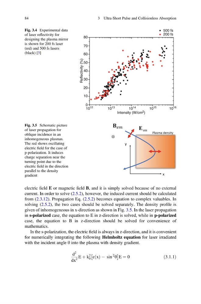
given of inhomogeneous in x-direction as shown in Fig. 3.5. In the laser propagation
in s-polarized case, the equation to E in z-direction is solved, while in p-polarized
case, the equation to B in z-direction should be solved for convenience of
mathematics.
In the s-polarization, the electric field is always in z-direction, and it is convenient
for numerically integrating the following Helmholtz equation for laser irradiated
with the incident angle θ into the plasma with density gradient.
d
2
dx
2
E þ k
2
0 ε x
ð Þ À sin
2
θ
Â
Ã
E ¼ 0
ð3:1:1Þ
80
500 fs
200 fs
70
60
50
Reflectivity (%)
40
30
20
10
0
10
12
10
13
10
14
Intensity (W/cm
2 )
10 15
10
16
Fig. 3.4 Experimental data
of laser reflectivity for
designing the plasma mirror
is shown for 200 fs laser
(red) and 500 fs lasers
(black) [3]
x
y
em
E
Plasma density
⊗
Fig. 3.5 Schematic picture
of laser propagation for
oblique incidence in an
inhomogeneous plasmas.
The red shows oscillating
electric field for the case of
p-polarization. It induces
charge separation near the
turning point due to the
electric field in the direction
parallel to the density
gradient
84
3 Ultra-Short Pulse and Collisionless Absorption
current. In order to solve (2.5.2), however, the induced current should be calculated
from (2.3.12). Propagation Eq. (2.5.2) becomes equation to complex valuables. In
solving (2.5.2), the two cases should be solved separately. The density profile is
given of inhomogeneous in x-direction as shown in Fig. 3.5. In the laser propagation
in s-polarized case, the equation to E in z-direction is solved, while in p-polarized
case, the equation to B in z-direction should be solved for convenience of
mathematics.
In the s-polarization, the electric field is always in z-direction, and it is convenient
for numerically integrating the following Helmholtz equation for laser irradiated
with the incident angle θ into the plasma with density gradient.
d
2
dx
2
E þ k
2
0 ε x
ð Þ À sin
2
θ
Â
Ã
E ¼ 0
ð3:1:1Þ
80
500 fs
200 fs
70
60
50
Reflectivity (%)
40
30
20
10
0
10
12
10
13
10
14
Intensity (W/cm
2 )
10 15
10
16
Fig. 3.4 Experimental data
of laser reflectivity for
designing the plasma mirror
is shown for 200 fs laser
(red) and 500 fs lasers
(black) [3]
x
y
em
E
Plasma density
⊗
Fig. 3.5 Schematic picture
of laser propagation for
oblique incidence in an
inhomogeneous plasmas.
The red shows oscillating
electric field for the case of
p-polarization. It induces
charge separation near the
turning point due to the
electric field in the direction
parallel to the density
gradient
84
3 Ultra-Short Pulse and Collisionless Absorption