

low-intensity experiment in [24], a small spot size and high-intensity experimental
result is reported [26]. In [26], the spot size is 1.7 μm in diameter and the laser
intensity 1.5 Â 10
21 W/cm
2 (a 0 ¼ 28). In the experiment, targets with different
thickness of pillar of diameter 55, 400, 600, and 1000 nm are irradiated, and it is
concluded that the case with 1 μm diameter pillar case is the best performance. With
1.7 μm focal spot, only one pillar of 1 μm is in the spot. It is also reported that 55 nm
nano-pillar array does not have a good performance. It may be considered that the
difference of the result in [26] is mainly due to the laser intensity which makes the
density of space between pillars higher than the critical density in early time.
7.8.3 Micro-tube Plasma Lenses
It is demonstrated with PIC simulation that laser irradiation in a hole of a micro-tube
made of carbon manufactured by the 3D laser printing micro-machining technology
can enhance the laser intensity in the hole, coupling of laser and matter, average
-45 fs
55 nm
0
0
100
200
325 x N ec
10
20 TV m -1
15
μm
15 μm
-15 fs
20 fs
55 fs
55 fs
55 nm
85 fs
120 fs
185 fs
285 fs
385 fs
b
a
c
1
0
0
-100
Intensity (a.u)
100
Time (fs)
200 300
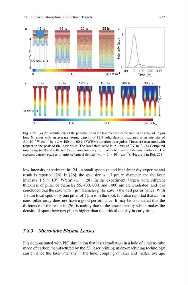
Fig. 7.35 (a) PIC simulations of the penetration of the laser beam electric field in an array of 15 μm
long Ni wires with an average atomic density of 12% solid density irradiated at an intensity of
5 Â 10
18 W cm
À2 by a λ ¼ 400 nm, 60 fs (FWHM) duration laser pulse. Times are measured with
respect to the peak of the laser pulse. The laser field scale is in units of TV m
À1
. (b) Computed
impinging (red) and reflected (blue) laser intensity. (c) Computed electron density evolution. The
electron density scale is in units of critical density (n ec ¼ 7 Â 10
21 cm
À3
). [Figure 1 in Ref. 25]
7.8 Efficient Absorption in Structured Targets
277
result is reported [26]. In [26], the spot size is 1.7 μm in diameter and the laser
intensity 1.5 Â 10
21 W/cm
2 (a 0 ¼ 28). In the experiment, targets with different
thickness of pillar of diameter 55, 400, 600, and 1000 nm are irradiated, and it is
concluded that the case with 1 μm diameter pillar case is the best performance. With
1.7 μm focal spot, only one pillar of 1 μm is in the spot. It is also reported that 55 nm
nano-pillar array does not have a good performance. It may be considered that the
difference of the result in [26] is mainly due to the laser intensity which makes the
density of space between pillars higher than the critical density in early time.
7.8.3 Micro-tube Plasma Lenses
It is demonstrated with PIC simulation that laser irradiation in a hole of a micro-tube
made of carbon manufactured by the 3D laser printing micro-machining technology
can enhance the laser intensity in the hole, coupling of laser and matter, average
-45 fs
55 nm
0
0
100
200
325 x N ec
10
20 TV m -1
15
μm
15 μm
-15 fs
20 fs
55 fs
55 fs
55 nm
85 fs
120 fs
185 fs
285 fs
385 fs
b
a
c
1
0
0
-100
Intensity (a.u)
100
Time (fs)
200 300
Fig. 7.35 (a) PIC simulations of the penetration of the laser beam electric field in an array of 15 μm
long Ni wires with an average atomic density of 12% solid density irradiated at an intensity of
5 Â 10
18 W cm
À2 by a λ ¼ 400 nm, 60 fs (FWHM) duration laser pulse. Times are measured with
respect to the peak of the laser pulse. The laser field scale is in units of TV m
À1
. (b) Computed
impinging (red) and reflected (blue) laser intensity. (c) Computed electron density evolution. The
electron density scale is in units of critical density (n ec ¼ 7 Â 10
21 cm
À3
). [Figure 1 in Ref. 25]
7.8 Efficient Absorption in Structured Targets
277