

In Fig. 7.27b, the number of hot electrons increases, and many of them are
reflected by the sheath potential as we can see many electron with negative
momentum. They are also confined in the target by the sheath potential generated
at the vacuum boundary of the foam plasma. By repeating the bounce due to the
reflection by both sheath fields, the ions are gradually accelerated. Since the mass of
the proton is relatively light compared to the carbon ions in the foam plasma, the
energy transfer is more efficient in the proton contamination plasma, showing about
10% energy gain in Fig. 7.24b.
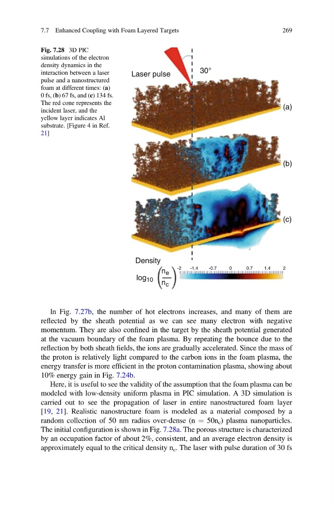
Here, it is useful to see the validity of the assumption that the foam plasma can be
modeled with low-density uniform plasma in PIC simulation. A 3D simulation is
carried out to see the propagation of laser in entire nanostructured foam layer
[19, 21]. Realistic nanostructure foam is modeled as a material composed by a
random collection of 50 nm radius over-dense (n ¼ 50n c ) plasma nanoparticles.
The initial configuration is shown in Fig. 7.28a. The porous structure is characterized
by an occupation factor of about 2%, consistent, and an average electron density is
approximately equal to the critical density n c . The laser with pulse duration of 30 fs
Laser pulse
(a)
(b)
(c)
Density
log 10
n e
-2
-1.4
-0.7
0
0.7
1.4
2
n c
30°
Fig. 7.28 3D PIC
simulations of the electron
density dynamics in the
interaction between a laser
pulse and a nanostructured
foam at different times: (a)
0 fs, (b) 67 fs, and (c) 134 fs.
The red cone represents the
incident laser, and the
yellow layer indicates Al
substrate. [Figure 4 in Ref.
21]
7.7 Enhanced Coupling with Foam Layered Targets
269
reflected by the sheath potential as we can see many electron with negative
momentum. They are also confined in the target by the sheath potential generated
at the vacuum boundary of the foam plasma. By repeating the bounce due to the
reflection by both sheath fields, the ions are gradually accelerated. Since the mass of
the proton is relatively light compared to the carbon ions in the foam plasma, the
energy transfer is more efficient in the proton contamination plasma, showing about
10% energy gain in Fig. 7.24b.
Here, it is useful to see the validity of the assumption that the foam plasma can be
modeled with low-density uniform plasma in PIC simulation. A 3D simulation is
carried out to see the propagation of laser in entire nanostructured foam layer
[19, 21]. Realistic nanostructure foam is modeled as a material composed by a
random collection of 50 nm radius over-dense (n ¼ 50n c ) plasma nanoparticles.
The initial configuration is shown in Fig. 7.28a. The porous structure is characterized
by an occupation factor of about 2%, consistent, and an average electron density is
approximately equal to the critical density n c . The laser with pulse duration of 30 fs
Laser pulse
(a)
(b)
(c)
Density
log 10
n e
-2
-1.4
-0.7
0
0.7
1.4
2
n c
30°
Fig. 7.28 3D PIC
simulations of the electron
density dynamics in the
interaction between a laser
pulse and a nanostructured
foam at different times: (a)
0 fs, (b) 67 fs, and (c) 134 fs.
The red cone represents the
incident laser, and the
yellow layer indicates Al
substrate. [Figure 4 in Ref.
21]
7.7 Enhanced Coupling with Foam Layered Targets
269