

called target normal sheath acceleration (TNSA), the physics of which will be
discussed in Volume 3. It has, however, pointed out the critical issues of the ion
acceleration, for example, an increase of energy of total ions and how to increase the
average energy of the ions.
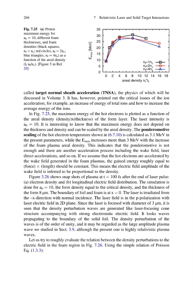
In Fig. 7.25, the maximum energy of the hot electrons is plotted as a function of
the areal density (density)x(thickness) of the form layer. The laser intensity is
a 0 ¼ 10. It is interesting to know that the maximum energy does not depend on
the thickness and density and can be scaled by the areal density. The ponderomotive
scaling of the hot electron temperature shown in (6.7.10) is calculated as 3.1 MeV in
the present parameters, while the E max increases more than 3 MeV with the increase
of the foam plasma areal density. This indicates that the ponderomotive is not
enough and there are another acceleration process including the wake field, laser
direct accelerations, and so on. If we assume that the hot electrons are accelerated by
the wake field generated in the foam plasmas, the gained energy roughly equal to
(force) Â (length) should be constant. This means the electric field amplitude of the
wake field is inferred to be proportional to the density.
Figure 3.26 shows snap shots of plasma at t ¼ 100 fs after the end of laser pulse:
(a) electron density and (b) longitudinal electric field distribution. The simulation is
done for a 0 ¼ 10, the form density equal to the critical density, and the thickness of
the form 8 μm. The boundary of foil and foam is at x ¼ 0. The laser is irradiated from
the –x-direction with normal incidence. The laser field is in the p-polarization with
laser electric field in 2D plane. Since the laser is focused with diameter of 3 μm, it is
seen that the density perturbation waves are generated like laser-focusing cone
structure accompanying with strong electrostatic electric field. It looks waves
propagating to the boundary of the solid foil. The density perturbation of the
waves is of the order of unity, and it may be regarded as the large amplitude plasma
wave we studied in Sect. 3.9, although the present one is highly relativistic plasma
waves.
Let us try to roughly evaluate the relation between the density perturbations to the
electric field in the foam region in Fig. 7.26. Using the simple relation of Poisson
Eq. (1.3.3):
35
30
25
20
15
10
E
max [MeV]
n f =1n c
n f =2n c
n f =4n c
5
0
0 2 4 6
areal density n f *I f
8 10 12 14 16 18
Fig. 7.25 (a) Proton
maximum energy for
a 0 ¼ 10, different foam
thicknesses, and foam
densities (black squares,
n f ¼ n c ; red circles, n f ¼ 2n c ;
blue triangles, n f ¼ 4n c ) as a
function of the areal density
(l f n f /n c ). [Figure 5 in Ref.
20]
266
7 Relativistic Laser and Solid Target Interactions
discussed in Volume 3. It has, however, pointed out the critical issues of the ion
acceleration, for example, an increase of energy of total ions and how to increase the
average energy of the ions.
In Fig. 7.25, the maximum energy of the hot electrons is plotted as a function of
the areal density (density)x(thickness) of the form layer. The laser intensity is
a 0 ¼ 10. It is interesting to know that the maximum energy does not depend on
the thickness and density and can be scaled by the areal density. The ponderomotive
scaling of the hot electron temperature shown in (6.7.10) is calculated as 3.1 MeV in
the present parameters, while the E max increases more than 3 MeV with the increase
of the foam plasma areal density. This indicates that the ponderomotive is not
enough and there are another acceleration process including the wake field, laser
direct accelerations, and so on. If we assume that the hot electrons are accelerated by
the wake field generated in the foam plasmas, the gained energy roughly equal to
(force) Â (length) should be constant. This means the electric field amplitude of the
wake field is inferred to be proportional to the density.
Figure 3.26 shows snap shots of plasma at t ¼ 100 fs after the end of laser pulse:
(a) electron density and (b) longitudinal electric field distribution. The simulation is
done for a 0 ¼ 10, the form density equal to the critical density, and the thickness of
the form 8 μm. The boundary of foil and foam is at x ¼ 0. The laser is irradiated from
the –x-direction with normal incidence. The laser field is in the p-polarization with
laser electric field in 2D plane. Since the laser is focused with diameter of 3 μm, it is
seen that the density perturbation waves are generated like laser-focusing cone
structure accompanying with strong electrostatic electric field. It looks waves
propagating to the boundary of the solid foil. The density perturbation of the
waves is of the order of unity, and it may be regarded as the large amplitude plasma
wave we studied in Sect. 3.9, although the present one is highly relativistic plasma
waves.
Let us try to roughly evaluate the relation between the density perturbations to the
electric field in the foam region in Fig. 7.26. Using the simple relation of Poisson
Eq. (1.3.3):
35
30
25
20
15
10
E
max [MeV]
n f =1n c
n f =2n c
n f =4n c
5
0
0 2 4 6
areal density n f *I f
8 10 12 14 16 18
Fig. 7.25 (a) Proton
maximum energy for
a 0 ¼ 10, different foam
thicknesses, and foam
densities (black squares,
n f ¼ n c ; red circles, n f ¼ 2n c ;
blue triangles, n f ¼ 4n c ) as a
function of the areal density
(l f n f /n c ). [Figure 5 in Ref.
20]
266
7 Relativistic Laser and Solid Target Interactions