

observed in the laboratory as shown in (5.2.34a). The light is emitted predominantly
toward the direction of relativistic motion. The angular dependence of the beaming is
easily obtained from Lorentz transformation of velocity shown in Sect. 5.1.
The narrowing of the angle enhances the intensity. We obtain the relation of the
enhancement factor dθ/dθ
0 in the following form after taking derivative of (5.2.34a):
dθ
cos 2 θ
¼
1
γ 0
β 0 cos θ
0
þ 1
β 0 þ cos θ
0
ð
Þ
2
dθ
0
ð5:4:16Þ
Coupling (5.2.34a) and (5.4.16), we obtain the intensity conversion from the moving
frame to the laboratory frame. (5.4.16) shows that all of the lights emitted with a
finite angle θ
0 in the moving frame are observed only within the angle θ < 1/γ 0 in the
laboratory frame for relativistic motion, β 0 ~ 1. In Fig. 5.15, the angle dependence of
the intensity in the moving frame and laboratory frame is plotted for two cases where
the acceleration is on the axis (cf; dipole emission) and perpendicular to the axis (cf;
synchrotron emission).
Consider Doppler shift of radiation emitted in the moving frame with the frequency ω
0 . Rewriting the relation (5.2.24) to the case with emission angle θ, we
obtain
ω ¼
ω
0
γ 0 1 À β 0 cosθ
ð
Þ
¼
1 À β 0
ð
Þ 1 þ β 0
ð
Þ
½
1=2
1 À β 0 cosθ
ð
Þ
ω
0
ð5:4:17Þ
F (x)
1
0 0.29
1
2
3
4
10
14
Critical Energy
Ring Energy 1 GeV
Typical SR output curve
Dipole Field 1.2 Tesla
10
12
10
10
10
8
10
6
10
4
10
2
10
0
10
-4 10
-3 10
-2 10
-1 10
0 10
1
Photon Energy / eV
Photons/sec/mrad/Amp/0.1% BW
10
2
10
3 10
4 10
5
x
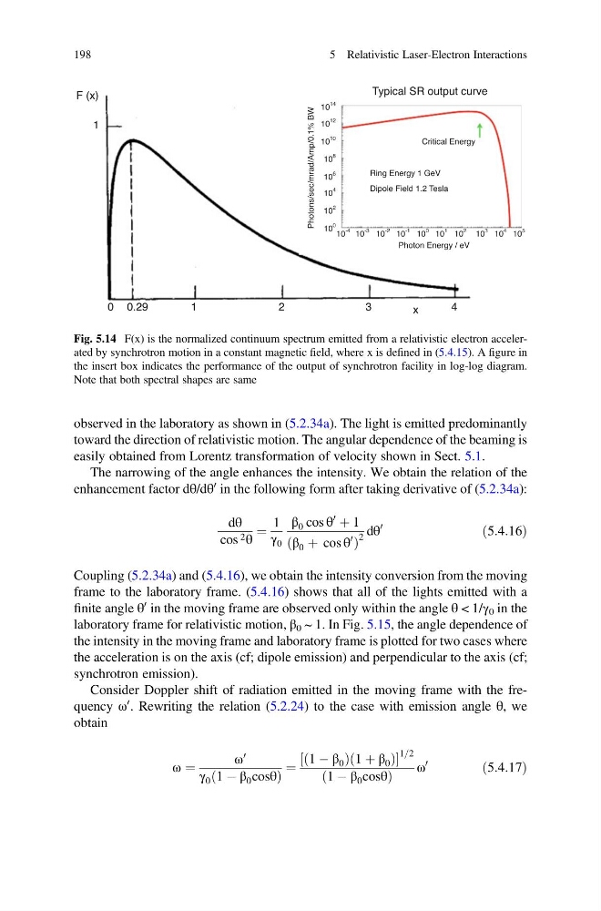
Fig. 5.14 F(x) is the normalized continuum spectrum emitted from a relativistic electron accelerated by synchrotron motion in a constant magnetic field, where x is defined in (5.4.15). A figure in
the insert box indicates the performance of the output of synchrotron facility in log-log diagram.
Note that both spectral shapes are same
198
5 Relativistic Laser-Electron Interactions
toward the direction of relativistic motion. The angular dependence of the beaming is
easily obtained from Lorentz transformation of velocity shown in Sect. 5.1.
The narrowing of the angle enhances the intensity. We obtain the relation of the
enhancement factor dθ/dθ
0 in the following form after taking derivative of (5.2.34a):
dθ
cos 2 θ
¼
1
γ 0
β 0 cos θ
0
þ 1
β 0 þ cos θ
0
ð
Þ
2
dθ
0
ð5:4:16Þ
Coupling (5.2.34a) and (5.4.16), we obtain the intensity conversion from the moving
frame to the laboratory frame. (5.4.16) shows that all of the lights emitted with a
finite angle θ
0 in the moving frame are observed only within the angle θ < 1/γ 0 in the
laboratory frame for relativistic motion, β 0 ~ 1. In Fig. 5.15, the angle dependence of
the intensity in the moving frame and laboratory frame is plotted for two cases where
the acceleration is on the axis (cf; dipole emission) and perpendicular to the axis (cf;
synchrotron emission).
Consider Doppler shift of radiation emitted in the moving frame with the frequency ω
0 . Rewriting the relation (5.2.24) to the case with emission angle θ, we
obtain
ω ¼
ω
0
γ 0 1 À β 0 cosθ
ð
Þ
¼
1 À β 0
ð
Þ 1 þ β 0
ð
Þ
½
1=2
1 À β 0 cosθ
ð
Þ
ω
0
ð5:4:17Þ
F (x)
1
0 0.29
1
2
3
4
10
14
Critical Energy
Ring Energy 1 GeV
Typical SR output curve
Dipole Field 1.2 Tesla
10
12
10
10
10
8
10
6
10
4
10
2
10
0
10
-4 10
-3 10
-2 10
-1 10
0 10
1
Photon Energy / eV
Photons/sec/mrad/Amp/0.1% BW
10
2
10
3 10
4 10
5
x
Fig. 5.14 F(x) is the normalized continuum spectrum emitted from a relativistic electron accelerated by synchrotron motion in a constant magnetic field, where x is defined in (5.4.15). A figure in
the insert box indicates the performance of the output of synchrotron facility in log-log diagram.
Note that both spectral shapes are same
198
5 Relativistic Laser-Electron Interactions