

470
V. Radeka
measurement, and usually plays a dominant role. In contrast, (2) with charge
amplifiers followed by filtering, the contribution of this noise (then usually referred
to as “parallel noise”) can be made negligible in most cases, by avoiding the
low frequency part of the spectrum (by using a short peaking time, Fig. 10.14).
Correlated double sampling (CDS) is one form of filtering.
10.8 Some Basic Signal Processing and Detector Readout
Circuits
10.8.1 Charge Amplifier Configuration
In the most basic charge amplifier feedback configuration only two transistors
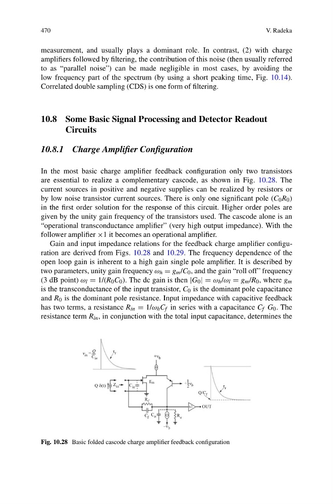
are essential to realize a complementary cascode, as shown in Fig. 10.28. The
current sources in positive and negative supplies can be realized by resistors or
by low noise transistor current sources. There is only one significant pole (C 0 R 0 )
in the first order solution for the response of this circuit. Higher order poles are
given by the unity gain frequency of the transistors used. The cascode alone is an
“operational transconductance amplifier” (very high output impedance). With the
follower amplifier ×1 it becomes an operational amplifier.
Gain and input impedance relations for the feedback charge amplifier configuration are derived from Figs. 10.28 and 10.29. The frequency dependence of the
open loop gain is inherent to a high gain single pole amplifier. It is described by
two parameters, unity gain frequency ω h = g m /C 0 , and the gain “roll off” frequency
(3 dB point) ω l = 1/(R 0 C 0 ). The dc gain is then |G 0 | = ω h /ω l = g m /R 0 , where g m
is the transconductance of the input transistor, C 0 is the dominant pole capacitance
and R 0 is the dominant pole resistance. Input impedance with capacitive feedback
has two terms, a resistance R in = 1/ω h C f in series with a capacitance C f G 0 . The
resistance term R in , in conjunction with the total input capacitance, determines the
ν in
ν b
C in
τ r
τ r
+v b
–v b
g m
R f
C f
Q/C f
C o
R o
x1
OUT
C in
Z in
Q δ(t)
= Q
+ 1
2
Fig. 10.28 Basic folded cascode charge amplifier feedback configuration
V. Radeka
measurement, and usually plays a dominant role. In contrast, (2) with charge
amplifiers followed by filtering, the contribution of this noise (then usually referred
to as “parallel noise”) can be made negligible in most cases, by avoiding the
low frequency part of the spectrum (by using a short peaking time, Fig. 10.14).
Correlated double sampling (CDS) is one form of filtering.
10.8 Some Basic Signal Processing and Detector Readout
Circuits
10.8.1 Charge Amplifier Configuration
In the most basic charge amplifier feedback configuration only two transistors
are essential to realize a complementary cascode, as shown in Fig. 10.28. The
current sources in positive and negative supplies can be realized by resistors or
by low noise transistor current sources. There is only one significant pole (C 0 R 0 )
in the first order solution for the response of this circuit. Higher order poles are
given by the unity gain frequency of the transistors used. The cascode alone is an
“operational transconductance amplifier” (very high output impedance). With the
follower amplifier ×1 it becomes an operational amplifier.
Gain and input impedance relations for the feedback charge amplifier configuration are derived from Figs. 10.28 and 10.29. The frequency dependence of the
open loop gain is inherent to a high gain single pole amplifier. It is described by
two parameters, unity gain frequency ω h = g m /C 0 , and the gain “roll off” frequency
(3 dB point) ω l = 1/(R 0 C 0 ). The dc gain is then |G 0 | = ω h /ω l = g m /R 0 , where g m
is the transconductance of the input transistor, C 0 is the dominant pole capacitance
and R 0 is the dominant pole resistance. Input impedance with capacitive feedback
has two terms, a resistance R in = 1/ω h C f in series with a capacitance C f G 0 . The
resistance term R in , in conjunction with the total input capacitance, determines the
ν in
ν b
C in
τ r
τ r
+v b
–v b
g m
R f
C f
Q/C f
C o
R o
x1
OUT
C in
Z in
Q δ(t)
= Q
+ 1
2
Fig. 10.28 Basic folded cascode charge amplifier feedback configuration