

10 Signal Processing for Particle Detectors
467
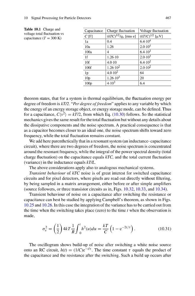
Table 10.1 Charge and
voltage total fluctuation vs
capacitance (T = 300 K)
Capacitance Charge fluctuation Voltage fluctuation
C [F]
(kTC) 1/2 /q e [rms e] (kT/C) 1/2 [μV]
1a
0.4
6.4·10 4
10a
1.26
2.0·10 4
100a
4
6.4·10 3
1f
1.26·10
2.0·10 3
10f
4.0·10
6.4·10 2
100f
1.26·10 2
2.0·10 2
1p
4.0·10 2
64
10p
1.26·10 3
20
100p
4·10 3
6.4
theorem states, that for a system in thermal equilibrium, the fluctuation energy per
degree of freedom is kT/2. “Per degree of freedom” applies to any variable by which
the energy of an energy storage object, or energy storage mode, can be defined. Thus
for a capacitance, C 2 = kT/2, from which Eq. (10.30) follows. So the statistical
mechanics gives the same result for the total fluctuation but without any details about
the dissipative components and the noise spectrum. A practical consequence is that
as a capacitor becomes closer to an ideal one, the noise spectrum shifts toward zero
frequency, while the total fluctuation remains constant.
We add here parenthetically that in a resonant system (an inductance- capacitance
circuit), where there are two degrees of freedom, the noise spectrum is concentrated
around the resonant frequency, while the integral of the power spectral density (total
charge fluctuation) on the capacitance equals kTC, and the total current fluctuation
(variance) in the inductance equals kT/L.
The above considerations apply also to analogous mechanical systems.
Transient behaviour of kTC noise is of great interest for switched capacitance
circuits and for pixel detectors, where pixels are read out directly without filtering,
by being sampled in a matrix arrangement, either before or after simple amplifiers
(source followers, or three transistor circuits as in, Figs. 10.32, 10.33, and 10.34).
Transient behaviour of noise on a capacitance after switching the resistance or
capacitance can best be studied by applying Campbell’s theorem, as shown in Figs.
10.25 and 10.26. In this case the integration of the variance has to be carried out from
the time when the switching takes place (zero) to the time t when the observation is
made,
σ
2
v =
1
2
4kT
1
R
t
0
h
2 (u)du =
kT
C
1 − e
−2t/τ
.
(10.31)
The oscillogram shows build-up of noise after switching a white noise source
onto an RC circuit, h(t) = (1/C)e −t/τ . The time constant τ equals the product of
the capacitance and the resistance after the switching. Such a build up occurs after
467
Table 10.1 Charge and
voltage total fluctuation vs
capacitance (T = 300 K)
Capacitance Charge fluctuation Voltage fluctuation
C [F]
(kTC) 1/2 /q e [rms e] (kT/C) 1/2 [μV]
1a
0.4
6.4·10 4
10a
1.26
2.0·10 4
100a
4
6.4·10 3
1f
1.26·10
2.0·10 3
10f
4.0·10
6.4·10 2
100f
1.26·10 2
2.0·10 2
1p
4.0·10 2
64
10p
1.26·10 3
20
100p
4·10 3
6.4
theorem states, that for a system in thermal equilibrium, the fluctuation energy per
degree of freedom is kT/2. “Per degree of freedom” applies to any variable by which
the energy of an energy storage object, or energy storage mode, can be defined. Thus
for a capacitance, C 2 = kT/2, from which Eq. (10.30) follows. So the statistical
mechanics gives the same result for the total fluctuation but without any details about
the dissipative components and the noise spectrum. A practical consequence is that
as a capacitor becomes closer to an ideal one, the noise spectrum shifts toward zero
frequency, while the total fluctuation remains constant.
We add here parenthetically that in a resonant system (an inductance- capacitance
circuit), where there are two degrees of freedom, the noise spectrum is concentrated
around the resonant frequency, while the integral of the power spectral density (total
charge fluctuation) on the capacitance equals kTC, and the total current fluctuation
(variance) in the inductance equals kT/L.
The above considerations apply also to analogous mechanical systems.
Transient behaviour of kTC noise is of great interest for switched capacitance
circuits and for pixel detectors, where pixels are read out directly without filtering,
by being sampled in a matrix arrangement, either before or after simple amplifiers
(source followers, or three transistor circuits as in, Figs. 10.32, 10.33, and 10.34).
Transient behaviour of noise on a capacitance after switching the resistance or
capacitance can best be studied by applying Campbell’s theorem, as shown in Figs.
10.25 and 10.26. In this case the integration of the variance has to be carried out from
the time when the switching takes place (zero) to the time t when the observation is
made,
σ
2
v =
1
2
4kT
1
R
t
0
h
2 (u)du =
kT
C
1 − e
−2t/τ
.
(10.31)
The oscillogram shows build-up of noise after switching a white noise source
onto an RC circuit, h(t) = (1/C)e −t/τ . The time constant τ equals the product of
the capacitance and the resistance after the switching. Such a build up occurs after