

10 Signal Processing for Particle Detectors
463
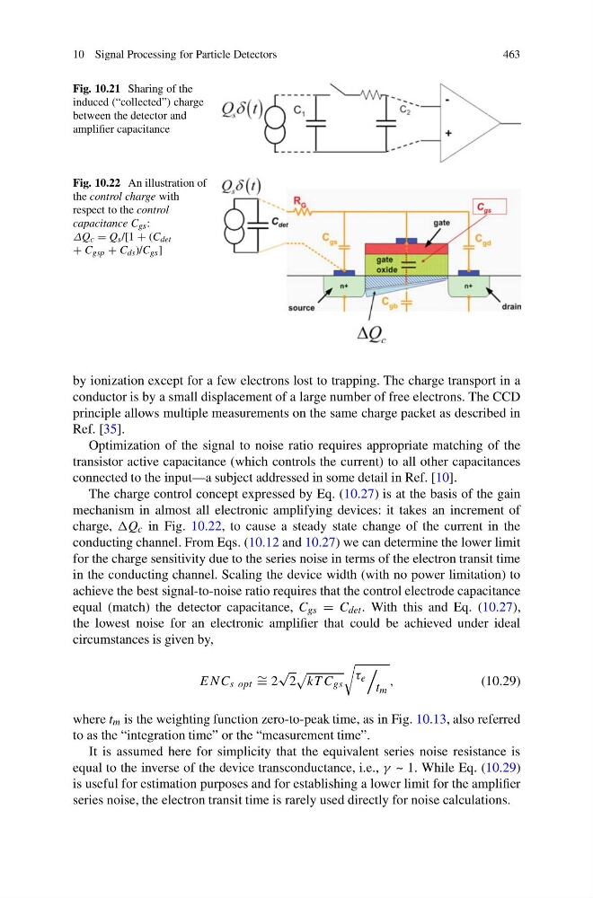
Fig. 10.21 Sharing of the
induced (“collected”) charge
between the detector and
amplifier capacitance
Fig. 10.22 An illustration of
the control charge with
respect to the control
capacitance C gs :
ΔQ c = Q s /[1 + (C det
+ C gsp + C ds )/C gs ]
by ionization except for a few electrons lost to trapping. The charge transport in a
conductor is by a small displacement of a large number of free electrons. The CCD
principle allows multiple measurements on the same charge packet as described in
Ref. [35].
Optimization of the signal to noise ratio requires appropriate matching of the
transistor active capacitance (which controls the current) to all other capacitances
connected to the input—a subject addressed in some detail in Ref. [10].
The charge control concept expressed by Eq. (10.27) is at the basis of the gain
mechanism in almost all electronic amplifying devices: it takes an increment of
charge, c in Fig. 10.22, to cause a steady state change of the current in the
conducting channel. From Eqs. (10.12 and 10.27) we can determine the lower limit
for the charge sensitivity due to the series noise in terms of the electron transit time
in the conducting channel. Scaling the device width (with no power limitation) to
achieve the best signal-to-noise ratio requires that the control electrode capacitance
equal (match) the detector capacitance, C gs = C det . With this and Eq. (10.27),
the lowest noise for an electronic amplifier that could be achieved under ideal
circumstances is given by,
ENC s opt ∼ = 2
√
2
kT C gs
τ e
t m
,
(10.29)
where t m is the weighting function zero-to-peak time, as in Fig. 10.13, also referred
to as the “integration time” or the “measurement time”.
It is assumed here for simplicity that the equivalent series noise resistance is
equal to the inverse of the device transconductance, i.e., γ ~ 1. While Eq. (10.29)
is useful for estimation purposes and for establishing a lower limit for the amplifier
series noise, the electron transit time is rarely used directly for noise calculations.
463
Fig. 10.21 Sharing of the
induced (“collected”) charge
between the detector and
amplifier capacitance
Fig. 10.22 An illustration of
the control charge with
respect to the control
capacitance C gs :
ΔQ c = Q s /[1 + (C det
+ C gsp + C ds )/C gs ]
by ionization except for a few electrons lost to trapping. The charge transport in a
conductor is by a small displacement of a large number of free electrons. The CCD
principle allows multiple measurements on the same charge packet as described in
Ref. [35].
Optimization of the signal to noise ratio requires appropriate matching of the
transistor active capacitance (which controls the current) to all other capacitances
connected to the input—a subject addressed in some detail in Ref. [10].
The charge control concept expressed by Eq. (10.27) is at the basis of the gain
mechanism in almost all electronic amplifying devices: it takes an increment of
charge, c in Fig. 10.22, to cause a steady state change of the current in the
conducting channel. From Eqs. (10.12 and 10.27) we can determine the lower limit
for the charge sensitivity due to the series noise in terms of the electron transit time
in the conducting channel. Scaling the device width (with no power limitation) to
achieve the best signal-to-noise ratio requires that the control electrode capacitance
equal (match) the detector capacitance, C gs = C det . With this and Eq. (10.27),
the lowest noise for an electronic amplifier that could be achieved under ideal
circumstances is given by,
ENC s opt ∼ = 2
√
2
kT C gs
τ e
t m
,
(10.29)
where t m is the weighting function zero-to-peak time, as in Fig. 10.13, also referred
to as the “integration time” or the “measurement time”.
It is assumed here for simplicity that the equivalent series noise resistance is
equal to the inverse of the device transconductance, i.e., γ ~ 1. While Eq. (10.29)
is useful for estimation purposes and for establishing a lower limit for the amplifier
series noise, the electron transit time is rarely used directly for noise calculations.