

7 Particle Detectors and Detector Systems
319
0
10
20
30
40
0
1 0
2 0
3 0
4 0
5 0
Air Spacing (mil)
Relative Intensity
4 GeV
3 GeV
2 GeV
1 GeV
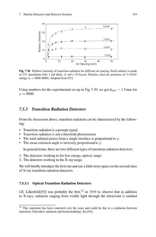
Fig. 7.30 Relative intensity of transition radiation for different air spacing. Each radiator is made
of 231 aluminium foils 1 mil thick. (1 mil = 25.4 μm). Particles used are positrons of 1–4 GeV
energy (γ = 2000–8000). Adapted from [91]
Using numbers for the experimental set-up in Fig. 7.30, we get d max ∼ 1.5 mm for
γ = 8000.
7.5.3 Transition Radiation Detectors
From the discussion above, transition radiation can be characterized by the following:
• Transition radiation is a prompt signal.
• Transition radiation is not a threshold phenomenon.
• The total radiated power from a single interface is proportional to γ .
• The mean emission angle is inversely proportional to γ .
In general terms, there are two different types of transition radiation detectors:
1. The detectors working in the low energy, optical, range.
2. The detectors working in the X-ray range.
We will briefly introduce the first one and use a little more space on the second class
of X-ray transition radiation detectors.
7.5.3.1 Optical Transition Radiation Detectors
J.E. Lilienfeld [92] was probably the first, 22 in 1919 to observe that in addition
to X-rays, radiation ranging from visible light through the ultraviolet is emitted
22 This statement has been contested over the years and could be due to a confusion between
transition, Cherenkov radiation and bremsstrahlung. See [93].
319
0
10
20
30
40
0
1 0
2 0
3 0
4 0
5 0
Air Spacing (mil)
Relative Intensity
4 GeV
3 GeV
2 GeV
1 GeV
Fig. 7.30 Relative intensity of transition radiation for different air spacing. Each radiator is made
of 231 aluminium foils 1 mil thick. (1 mil = 25.4 μm). Particles used are positrons of 1–4 GeV
energy (γ = 2000–8000). Adapted from [91]
Using numbers for the experimental set-up in Fig. 7.30, we get d max ∼ 1.5 mm for
γ = 8000.
7.5.3 Transition Radiation Detectors
From the discussion above, transition radiation can be characterized by the following:
• Transition radiation is a prompt signal.
• Transition radiation is not a threshold phenomenon.
• The total radiated power from a single interface is proportional to γ .
• The mean emission angle is inversely proportional to γ .
In general terms, there are two different types of transition radiation detectors:
1. The detectors working in the low energy, optical, range.
2. The detectors working in the X-ray range.
We will briefly introduce the first one and use a little more space on the second class
of X-ray transition radiation detectors.
7.5.3.1 Optical Transition Radiation Detectors
J.E. Lilienfeld [92] was probably the first, 22 in 1919 to observe that in addition
to X-rays, radiation ranging from visible light through the ultraviolet is emitted
22 This statement has been contested over the years and could be due to a confusion between
transition, Cherenkov radiation and bremsstrahlung. See [93].