

7 Particle Detectors and Detector Systems
313
220
200
180
160
140
120
100
80
60
40
20
0
Momentum (GeV/c)
10 2
10
15
0
0
100
200
Background
Signal
Number of photons
300
400
500
5
10 15 20
Radius (mm)
25 30 35 40
20
25
30
Cherenkov Angle (mrad)
35
40
45
50
K
p
μ
p
(a)
(b)
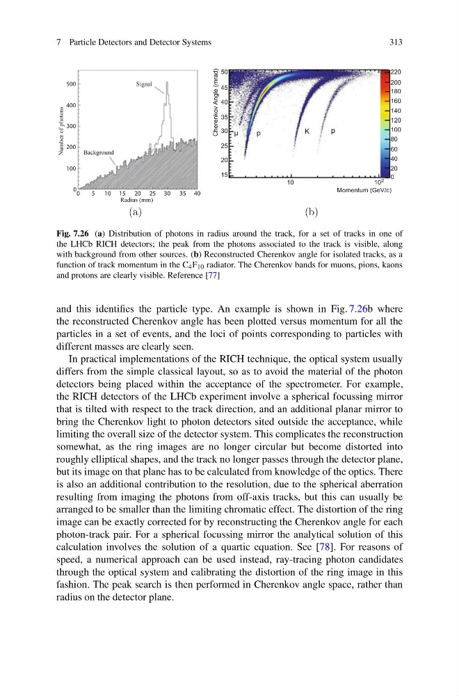
Fig. 7.26 (a) Distribution of photons in radius around the track, for a set of tracks in one of
the LHCb RICH detectors; the peak from the photons associated to the track is visible, along
with background from other sources. (b) Reconstructed Cherenkov angle for isolated tracks, as a
function of track momentum in the C 4 F 10 radiator. The Cherenkov bands for muons, pions, kaons
and protons are clearly visible. Reference [77]
and this identifies the particle type. An example is shown in Fig. 7.26b where
the reconstructed Cherenkov angle has been plotted versus momentum for all the
particles in a set of events, and the loci of points corresponding to particles with
different masses are clearly seen.
In practical implementations of the RICH technique, the optical system usually
differs from the simple classical layout, so as to avoid the material of the photon
detectors being placed within the acceptance of the spectrometer. For example,
the RICH detectors of the LHCb experiment involve a spherical focussing mirror
that is tilted with respect to the track direction, and an additional planar mirror to
bring the Cherenkov light to photon detectors sited outside the acceptance, while
limiting the overall size of the detector system. This complicates the reconstruction
somewhat, as the ring images are no longer circular but become distorted into
roughly elliptical shapes, and the track no longer passes through the detector plane,
but its image on that plane has to be calculated from knowledge of the optics. There
is also an additional contribution to the resolution, due to the spherical aberration
resulting from imaging the photons from off-axis tracks, but this can usually be
arranged to be smaller than the limiting chromatic effect. The distortion of the ring
image can be exactly corrected for by reconstructing the Cherenkov angle for each
photon-track pair. For a spherical focussing mirror the analytical solution of this
calculation involves the solution of a quartic equation. See [78]. For reasons of
speed, a numerical approach can be used instead, ray-tracing photon candidates
through the optical system and calibrating the distortion of the ring image in this
fashion. The peak search is then performed in Cherenkov angle space, rather than
radius on the detector plane.
313
220
200
180
160
140
120
100
80
60
40
20
0
Momentum (GeV/c)
10 2
10
15
0
0
100
200
Background
Signal
Number of photons
300
400
500
5
10 15 20
Radius (mm)
25 30 35 40
20
25
30
Cherenkov Angle (mrad)
35
40
45
50
K
p
μ
p
(a)
(b)
Fig. 7.26 (a) Distribution of photons in radius around the track, for a set of tracks in one of
the LHCb RICH detectors; the peak from the photons associated to the track is visible, along
with background from other sources. (b) Reconstructed Cherenkov angle for isolated tracks, as a
function of track momentum in the C 4 F 10 radiator. The Cherenkov bands for muons, pions, kaons
and protons are clearly visible. Reference [77]
and this identifies the particle type. An example is shown in Fig. 7.26b where
the reconstructed Cherenkov angle has been plotted versus momentum for all the
particles in a set of events, and the loci of points corresponding to particles with
different masses are clearly seen.
In practical implementations of the RICH technique, the optical system usually
differs from the simple classical layout, so as to avoid the material of the photon
detectors being placed within the acceptance of the spectrometer. For example,
the RICH detectors of the LHCb experiment involve a spherical focussing mirror
that is tilted with respect to the track direction, and an additional planar mirror to
bring the Cherenkov light to photon detectors sited outside the acceptance, while
limiting the overall size of the detector system. This complicates the reconstruction
somewhat, as the ring images are no longer circular but become distorted into
roughly elliptical shapes, and the track no longer passes through the detector plane,
but its image on that plane has to be calculated from knowledge of the optics. There
is also an additional contribution to the resolution, due to the spherical aberration
resulting from imaging the photons from off-axis tracks, but this can usually be
arranged to be smaller than the limiting chromatic effect. The distortion of the ring
image can be exactly corrected for by reconstructing the Cherenkov angle for each
photon-track pair. For a spherical focussing mirror the analytical solution of this
calculation involves the solution of a quartic equation. See [78]. For reasons of
speed, a numerical approach can be used instead, ray-tracing photon candidates
through the optical system and calibrating the distortion of the ring image in this
fashion. The peak search is then performed in Cherenkov angle space, rather than
radius on the detector plane.