

7 Particle Detectors and Detector Systems
311
Test
object
Grating
(Ronchi Ruling)
Pupil
relay
Observation
plane
(a)
(b)
(c)
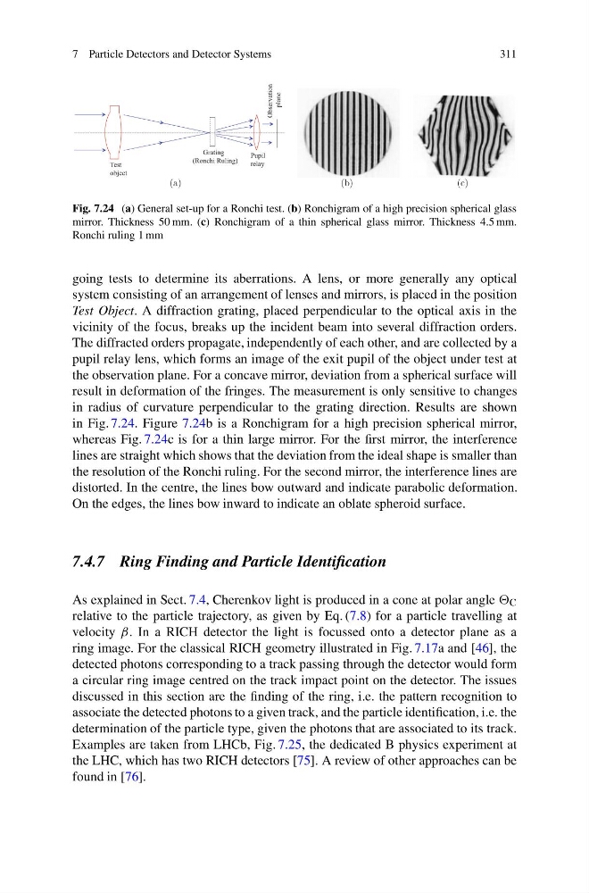
Fig. 7.24 (a) General set-up for a Ronchi test. (b) Ronchigram of a high precision spherical glass
mirror. Thickness 50 mm. (c) Ronchigram of a thin spherical glass mirror. Thickness 4.5 mm.
Ronchi ruling 1 mm
going tests to determine its aberrations. A lens, or more generally any optical
system consisting of an arrangement of lenses and mirrors, is placed in the position
Test Object. A diffraction grating, placed perpendicular to the optical axis in the
vicinity of the focus, breaks up the incident beam into several diffraction orders.
The diffracted orders propagate, independently of each other, and are collected by a
pupil relay lens, which forms an image of the exit pupil of the object under test at
the observation plane. For a concave mirror, deviation from a spherical surface will
result in deformation of the fringes. The measurement is only sensitive to changes
in radius of curvature perpendicular to the grating direction. Results are shown
in Fig. 7.24. Figure 7.24b is a Ronchigram for a high precision spherical mirror,
whereas Fig. 7.24c is for a thin large mirror. For the first mirror, the interference
lines are straight which shows that the deviation from the ideal shape is smaller than
the resolution of the Ronchi ruling. For the second mirror, the interference lines are
distorted. In the centre, the lines bow outward and indicate parabolic deformation.
On the edges, the lines bow inward to indicate an oblate spheroid surface.
7.4.7 Ring Finding and Particle Identification
As explained in Sect. 7.4, Cherenkov light is produced in a cone at polar angle C
relative to the particle trajectory, as given by Eq. (7.8) for a particle travelling at
velocity β. In a RICH detector the light is focussed onto a detector plane as a
ring image. For the classical RICH geometry illustrated in Fig. 7.17a and [46], the
detected photons corresponding to a track passing through the detector would form
a circular ring image centred on the track impact point on the detector. The issues
discussed in this section are the finding of the ring, i.e. the pattern recognition to
associate the detected photons to a given track, and the particle identification, i.e. the
determination of the particle type, given the photons that are associated to its track.
Examples are taken from LHCb, Fig. 7.25, the dedicated B physics experiment at
the LHC, which has two RICH detectors [75]. A review of other approaches can be
found in [76].
311
Test
object
Grating
(Ronchi Ruling)
Pupil
relay
Observation
plane
(a)
(b)
(c)
Fig. 7.24 (a) General set-up for a Ronchi test. (b) Ronchigram of a high precision spherical glass
mirror. Thickness 50 mm. (c) Ronchigram of a thin spherical glass mirror. Thickness 4.5 mm.
Ronchi ruling 1 mm
going tests to determine its aberrations. A lens, or more generally any optical
system consisting of an arrangement of lenses and mirrors, is placed in the position
Test Object. A diffraction grating, placed perpendicular to the optical axis in the
vicinity of the focus, breaks up the incident beam into several diffraction orders.
The diffracted orders propagate, independently of each other, and are collected by a
pupil relay lens, which forms an image of the exit pupil of the object under test at
the observation plane. For a concave mirror, deviation from a spherical surface will
result in deformation of the fringes. The measurement is only sensitive to changes
in radius of curvature perpendicular to the grating direction. Results are shown
in Fig. 7.24. Figure 7.24b is a Ronchigram for a high precision spherical mirror,
whereas Fig. 7.24c is for a thin large mirror. For the first mirror, the interference
lines are straight which shows that the deviation from the ideal shape is smaller than
the resolution of the Ronchi ruling. For the second mirror, the interference lines are
distorted. In the centre, the lines bow outward and indicate parabolic deformation.
On the edges, the lines bow inward to indicate an oblate spheroid surface.
7.4.7 Ring Finding and Particle Identification
As explained in Sect. 7.4, Cherenkov light is produced in a cone at polar angle C
relative to the particle trajectory, as given by Eq. (7.8) for a particle travelling at
velocity β. In a RICH detector the light is focussed onto a detector plane as a
ring image. For the classical RICH geometry illustrated in Fig. 7.17a and [46], the
detected photons corresponding to a track passing through the detector would form
a circular ring image centred on the track impact point on the detector. The issues
discussed in this section are the finding of the ring, i.e. the pattern recognition to
associate the detected photons to a given track, and the particle identification, i.e. the
determination of the particle type, given the photons that are associated to its track.
Examples are taken from LHCb, Fig. 7.25, the dedicated B physics experiment at
the LHC, which has two RICH detectors [75]. A review of other approaches can be
found in [76].