

7 Particle Detectors and Detector Systems
309
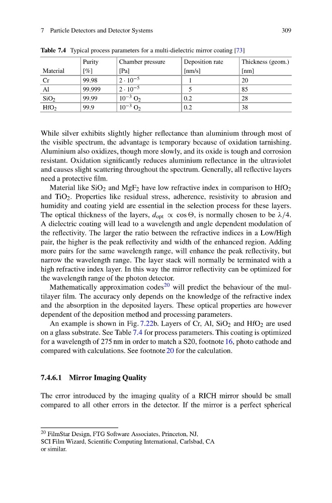
Table 7.4 Typical process parameters for a multi-dielectric mirror coating [73]
Purity
Chamber pressure
Deposition rate
Thickness (geom.)
Material
[%]
[Pa]
[nm/s]
[nm]
Cr
99.98
2 · 10 −5
1
20
Al
99.999
2 · 10 −5
5
85
SiO 2
99.99
10 −3 O 2
0.2
28
HfO 2
99.9
10 −3 O 2
0.2
38
While silver exhibits slightly higher reflectance than aluminium through most of
the visible spectrum, the advantage is temporary because of oxidation tarnishing.
Aluminium also oxidizes, though more slowly, and its oxide is tough and corrosion
resistant. Oxidation significantly reduces aluminium reflectance in the ultraviolet
and causes slight scattering throughout the spectrum. Generally, all reflective layers
need a protective film.
Material like SiO 2 and MgF 2 have low refractive index in comparison to HfO 2
and TiO 2 . Properties like residual stress, adherence, resistivity to abrasion and
humidity and coating yield are essential in the selection process for these layers.
The optical thickness of the layers, d opt ∝ cos , is normally chosen to be λ/4.
A dielectric coating will lead to a wavelength and angle dependent modulation of
the reflectivity. The larger the ratio between the refractive indices in a Low/High
pair, the higher is the peak reflectivity and width of the enhanced region. Adding
more pairs for the same wavelength range, will enhance the peak reflectivity, but
narrow the wavelength range. The layer stack will normally be terminated with a
high refractive index layer. In this way the mirror reflectivity can be optimized for
the wavelength range of the photon detector.
Mathematically approximation codes 20 will predict the behaviour of the multilayer film. The accuracy only depends on the knowledge of the refractive index
and the absorption in the deposited layers. These optical properties are however
dependent of the deposition method and processing parameters.
An example is shown in Fig. 7.22b. Layers of Cr, Al, SiO 2 and HfO 2 are used
on a glass substrate. See Table 7.4 for process parameters. This coating is optimized
for a wavelength of 275 nm in order to match a S20, footnote 16, photo cathode and
compared with calculations. See footnote 20 for the calculation.
7.4.6.1 Mirror Imaging Quality
The error introduced by the imaging quality of a RICH mirror should be small
compared to all other errors in the detector. If the mirror is a perfect spherical
20 FilmStar Design, FTG Software Associates, Princeton, NJ,
SCI Film Wizard, Scientific Computing International, Carlsbad, CA
or similar.
309
Table 7.4 Typical process parameters for a multi-dielectric mirror coating [73]
Purity
Chamber pressure
Deposition rate
Thickness (geom.)
Material
[%]
[Pa]
[nm/s]
[nm]
Cr
99.98
2 · 10 −5
1
20
Al
99.999
2 · 10 −5
5
85
SiO 2
99.99
10 −3 O 2
0.2
28
HfO 2
99.9
10 −3 O 2
0.2
38
While silver exhibits slightly higher reflectance than aluminium through most of
the visible spectrum, the advantage is temporary because of oxidation tarnishing.
Aluminium also oxidizes, though more slowly, and its oxide is tough and corrosion
resistant. Oxidation significantly reduces aluminium reflectance in the ultraviolet
and causes slight scattering throughout the spectrum. Generally, all reflective layers
need a protective film.
Material like SiO 2 and MgF 2 have low refractive index in comparison to HfO 2
and TiO 2 . Properties like residual stress, adherence, resistivity to abrasion and
humidity and coating yield are essential in the selection process for these layers.
The optical thickness of the layers, d opt ∝ cos , is normally chosen to be λ/4.
A dielectric coating will lead to a wavelength and angle dependent modulation of
the reflectivity. The larger the ratio between the refractive indices in a Low/High
pair, the higher is the peak reflectivity and width of the enhanced region. Adding
more pairs for the same wavelength range, will enhance the peak reflectivity, but
narrow the wavelength range. The layer stack will normally be terminated with a
high refractive index layer. In this way the mirror reflectivity can be optimized for
the wavelength range of the photon detector.
Mathematically approximation codes 20 will predict the behaviour of the multilayer film. The accuracy only depends on the knowledge of the refractive index
and the absorption in the deposited layers. These optical properties are however
dependent of the deposition method and processing parameters.
An example is shown in Fig. 7.22b. Layers of Cr, Al, SiO 2 and HfO 2 are used
on a glass substrate. See Table 7.4 for process parameters. This coating is optimized
for a wavelength of 275 nm in order to match a S20, footnote 16, photo cathode and
compared with calculations. See footnote 20 for the calculation.
7.4.6.1 Mirror Imaging Quality
The error introduced by the imaging quality of a RICH mirror should be small
compared to all other errors in the detector. If the mirror is a perfect spherical
20 FilmStar Design, FTG Software Associates, Princeton, NJ,
SCI Film Wizard, Scientific Computing International, Carlsbad, CA
or similar.