

308
R. Forty and O. Ullaland
substrates of diameter 500 and 5 mm thickness are compared. However, beryllium
is not a good reflector nor a good support for a reflecting surface. A thin glass face
is therefore required on the beryllium as support for the reflector [68]. This glass
surface can also be used to adjust the focal length of the mirror. The main challenge
is to use a glass which has the same thermal expansion coefficient as beryllium.
Thin and robust mirror substrates can be made as a sandwich assembly. The
kernel is normally a honeycomb or foam and the inner and outer skin are preformed
to about the right radius of curvature. The final adjustment is done at the assembly
stage or by reshaping, by polishing, the reflecting skin later. The skin can be
high strength carbon fibre sheets [69], easily formed Plexiglas [70] or simple metal
structures [71]. Glass with glass-foam kernel has also been built [72].
Glass is still the most used substrate for mirrors. It is easily shaped and machined
and the ageing behaviour is well known. Stresses in the material can be simply
relieved. It is also inert in most Cherenkov radiators. It is normally slumped to the
required shape and then polished to the final focal length. Its principal drawback is
the radiation length.
7.4.6 The Reflective Surface
The reflectivity of a surface is a function of the incident angle and energy of the light
and the dielectric structure of the surface. The principle is discussed in [40] and more
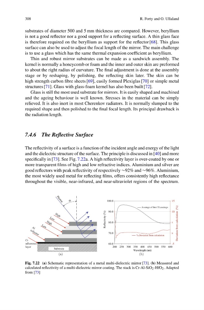
specifically in [73]. See Fig. 7.22a. A high reflectivity layer is over-coated by one or
more transparent films of high and low refractive indices. Aluminium and silver are
good reflectors with peak reflectivity of respectively ∼92% and ∼96%. Aluminium,
the most widely used metal for reflecting films, offers consistently high reflectance
throughout the visible, near-infrared, and near-ultraviolet regions of the spectrum.
Cr
adherence
layer
A l
re fl e c to r
H ig h
L o w
H ig h
L o w
P
h
o
t
o
n
Θ
Substrate
(a)
60.0
70.0
80.0
90.0
100.0
200 250 300 350 400 450 500 550 600
Wavelength (nm)
Reflectivity (%)
-5
0
5
10
15
Deviation from calculation (%)
Average of first 33 coatings
% Deviation from calculation
(b)
Fig. 7.22 (a) Schematic representation of a metal multi-dielectric mirror [73]. (b) Measured and
calculated reflectivity of a multi-dielectric mirror coating. The stack is Cr-Al-SiO 2 -HfO 2 . Adapted
from [73]
R. Forty and O. Ullaland
substrates of diameter 500 and 5 mm thickness are compared. However, beryllium
is not a good reflector nor a good support for a reflecting surface. A thin glass face
is therefore required on the beryllium as support for the reflector [68]. This glass
surface can also be used to adjust the focal length of the mirror. The main challenge
is to use a glass which has the same thermal expansion coefficient as beryllium.
Thin and robust mirror substrates can be made as a sandwich assembly. The
kernel is normally a honeycomb or foam and the inner and outer skin are preformed
to about the right radius of curvature. The final adjustment is done at the assembly
stage or by reshaping, by polishing, the reflecting skin later. The skin can be
high strength carbon fibre sheets [69], easily formed Plexiglas [70] or simple metal
structures [71]. Glass with glass-foam kernel has also been built [72].
Glass is still the most used substrate for mirrors. It is easily shaped and machined
and the ageing behaviour is well known. Stresses in the material can be simply
relieved. It is also inert in most Cherenkov radiators. It is normally slumped to the
required shape and then polished to the final focal length. Its principal drawback is
the radiation length.
7.4.6 The Reflective Surface
The reflectivity of a surface is a function of the incident angle and energy of the light
and the dielectric structure of the surface. The principle is discussed in [40] and more
specifically in [73]. See Fig. 7.22a. A high reflectivity layer is over-coated by one or
more transparent films of high and low refractive indices. Aluminium and silver are
good reflectors with peak reflectivity of respectively ∼92% and ∼96%. Aluminium,
the most widely used metal for reflecting films, offers consistently high reflectance
throughout the visible, near-infrared, and near-ultraviolet regions of the spectrum.
Cr
adherence
layer
A l
re fl e c to r
H ig h
L o w
H ig h
L o w
P
h
o
t
o
n
Θ
Substrate
(a)
60.0
70.0
80.0
90.0
100.0
200 250 300 350 400 450 500 550 600
Wavelength (nm)
Reflectivity (%)
-5
0
5
10
15
Deviation from calculation (%)
Average of first 33 coatings
% Deviation from calculation
(b)
Fig. 7.22 (a) Schematic representation of a metal multi-dielectric mirror [73]. (b) Measured and
calculated reflectivity of a multi-dielectric mirror coating. The stack is Cr-Al-SiO 2 -HfO 2 . Adapted
from [73]