

7 Particle Detectors and Detector Systems
283
0
0.0
0.2
0.4
Mass (GeV)
0.6
0.8
1.0
1.2
1
2
3
4
5
Momentum (GeV/c)
6
7
8
9 10
p
K
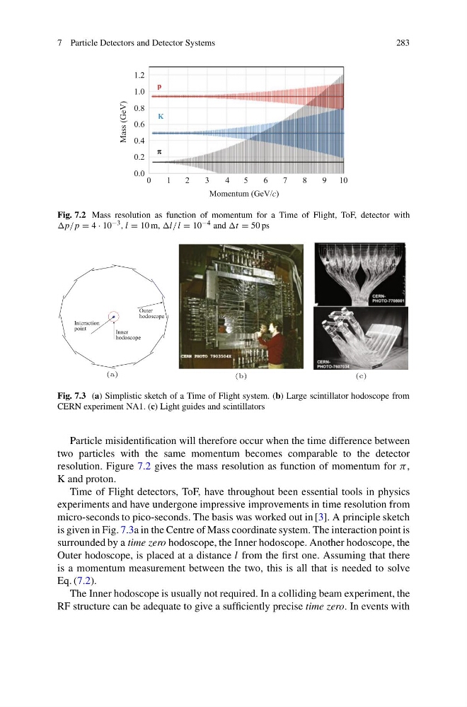
Fig. 7.2 Mass resolution as function of momentum for a Time of Flight, ToF, detector with
= 4 · 10 −3 , l = 10 m, l = 10 −4 and t = 50 ps
Interaction
point
Inner
hodoscope
Outer
hodoscope
(a)
(b)
(c)
Fig. 7.3 (a) Simplistic sketch of a Time of Flight system. (b) Large scintillator hodoscope from
CERN experiment NA1. (c) Light guides and scintillators
Particle misidentification will therefore occur when the time difference between
two particles with the same momentum becomes comparable to the detector
resolution. Figure 7.2 gives the mass resolution as function of momentum for π,
K and proton.
Time of Flight detectors, ToF, have throughout been essential tools in physics
experiments and have undergone impressive improvements in time resolution from
micro-seconds to pico-seconds. The basis was worked out in [3]. A principle sketch
is given in Fig. 7.3a in the Centre of Mass coordinate system. The interaction point is
surrounded by a time zero hodoscope, the Inner hodoscope. Another hodoscope, the
Outer hodoscope, is placed at a distance l from the first one. Assuming that there
is a momentum measurement between the two, this is all that is needed to solve
Eq. (7.2).
The Inner hodoscope is usually not required. In a colliding beam experiment, the
RF structure can be adequate to give a sufficiently precise time zero. In events with
283
0
0.0
0.2
0.4
Mass (GeV)
0.6
0.8
1.0
1.2
1
2
3
4
5
Momentum (GeV/c)
6
7
8
9 10
p
K
Fig. 7.2 Mass resolution as function of momentum for a Time of Flight, ToF, detector with
= 4 · 10 −3 , l = 10 m, l = 10 −4 and t = 50 ps
Interaction
point
Inner
hodoscope
Outer
hodoscope
(a)
(b)
(c)
Fig. 7.3 (a) Simplistic sketch of a Time of Flight system. (b) Large scintillator hodoscope from
CERN experiment NA1. (c) Light guides and scintillators
Particle misidentification will therefore occur when the time difference between
two particles with the same momentum becomes comparable to the detector
resolution. Figure 7.2 gives the mass resolution as function of momentum for π,
K and proton.
Time of Flight detectors, ToF, have throughout been essential tools in physics
experiments and have undergone impressive improvements in time resolution from
micro-seconds to pico-seconds. The basis was worked out in [3]. A principle sketch
is given in Fig. 7.3a in the Centre of Mass coordinate system. The interaction point is
surrounded by a time zero hodoscope, the Inner hodoscope. Another hodoscope, the
Outer hodoscope, is placed at a distance l from the first one. Assuming that there
is a momentum measurement between the two, this is all that is needed to solve
Eq. (7.2).
The Inner hodoscope is usually not required. In a colliding beam experiment, the
RF structure can be adequate to give a sufficiently precise time zero. In events with