

570
M. Lamont et al.
0
5
10
15
20
0.7
0.75
0.8
0.85
0.9
Time in collisions [h]
Geometric
Factor
F
leveling
no leveling
0
5
10
15
20
0.4
0.6
0.8
1
1.2
Time in collisions [h]
Luminosity [10
34
cm
−2
s
−1
]
leveling
no leveling
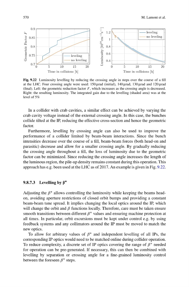
Fig. 9.22 Luminosity levelling by reducing the crossing angle in steps over the course of a fill
at the LHC. Four crossing angle were used: 150 μrad (initial), 140 μrad, 130 μrad and 120 μrad
(final). Left: the geometric reduction factor F , which increases as the crossing angle is decreased.
Right: the resulting luminosity. The integrated gain due to the levelling (shaded area) was at the
level of 5%
In a collider with crab cavities, a similar effect can be achieved by varying the
crab cavity voltage instead of the external crossing angle. In this case, the bunches
collide tilted at the IP, reducing the effective cross-section and hence the geometric
factor.
Furthermore, levelling by crossing angle can also be used to improve the
performance of a collider limited by beam-beam interactions. Since the bunch
intensities decrease over the course of a fill, beam-beam forces (both head-on and
parasitic) decrease and allow for a smaller crossing angle. By gradually reducing
the crossing angle throughout a fill, the loss of luminosity due to the geometric
factor can be minimized. Since reducing the crossing angle increases the length of
the luminous region, the pile-up density remains constant during this operation. This
approach has e.g. been used at the LHC as of 2017. An example is given in Fig. 9.22.
9.8.7.3 Levelling by β
∗
Adjusting the β ∗ allows controlling the luminosity while keeping the beams headon, avoiding aperture restrictions of closed orbit bumps and providing a constant
beam-beam tune spread. It implies changing the local optics around the IP, which
will change the orbit and β functions locally. Therefore, care must be taken ensure
smooth transitions between different β ∗ values and ensuring machine protection at
all times. In particular, orbit excursions must be kept under control e.g. by using
feedback systems and any collimators around the IP must be moved to match the
new optics.
To allow for arbitrary values of β ∗ and independent levelling of all IPs, the
corresponding IP optics would need to be matched online during collider operation.
To reduce complexity, a discrete set of IP optics covering the range of β ∗ needed
for operation can be pre-generated. If necessary, this can then be combined with
levelling by separation or crossing angle for a fine-grained luminosity control
between the foreseen β ∗ steps.
M. Lamont et al.
0
5
10
15
20
0.7
0.75
0.8
0.85
0.9
Time in collisions [h]
Geometric
Factor
F
leveling
no leveling
0
5
10
15
20
0.4
0.6
0.8
1
1.2
Time in collisions [h]
Luminosity [10
34
cm
−2
s
−1
]
leveling
no leveling
Fig. 9.22 Luminosity levelling by reducing the crossing angle in steps over the course of a fill
at the LHC. Four crossing angle were used: 150 μrad (initial), 140 μrad, 130 μrad and 120 μrad
(final). Left: the geometric reduction factor F , which increases as the crossing angle is decreased.
Right: the resulting luminosity. The integrated gain due to the levelling (shaded area) was at the
level of 5%
In a collider with crab cavities, a similar effect can be achieved by varying the
crab cavity voltage instead of the external crossing angle. In this case, the bunches
collide tilted at the IP, reducing the effective cross-section and hence the geometric
factor.
Furthermore, levelling by crossing angle can also be used to improve the
performance of a collider limited by beam-beam interactions. Since the bunch
intensities decrease over the course of a fill, beam-beam forces (both head-on and
parasitic) decrease and allow for a smaller crossing angle. By gradually reducing
the crossing angle throughout a fill, the loss of luminosity due to the geometric
factor can be minimized. Since reducing the crossing angle increases the length of
the luminous region, the pile-up density remains constant during this operation. This
approach has e.g. been used at the LHC as of 2017. An example is given in Fig. 9.22.
9.8.7.3 Levelling by β
∗
Adjusting the β ∗ allows controlling the luminosity while keeping the beams headon, avoiding aperture restrictions of closed orbit bumps and providing a constant
beam-beam tune spread. It implies changing the local optics around the IP, which
will change the orbit and β functions locally. Therefore, care must be taken ensure
smooth transitions between different β ∗ values and ensuring machine protection at
all times. In particular, orbit excursions must be kept under control e.g. by using
feedback systems and any collimators around the IP must be moved to match the
new optics.
To allow for arbitrary values of β ∗ and independent levelling of all IPs, the
corresponding IP optics would need to be matched online during collider operation.
To reduce complexity, a discrete set of IP optics covering the range of β ∗ needed
for operation can be pre-generated. If necessary, this can then be combined with
levelling by separation or crossing angle for a fine-grained luminosity control
between the foreseen β ∗ steps.