

554
M. Lamont et al.
9.7.4 Beam-Based Set-Up of Collimation
The previous section explained the criticality of correct collimator hierarchy. It
was shown that retraction values can be in the range of 100 μm. Collimators must
be centred around the beam with an accuracy that is a fraction of the collimator
retraction. Tolerances for collimator settings can then be in the range of a few 10’s
of μm. However, the exact beam position and size are not known a priori with this
accuracy. Collimators are therefore set up in a beam-based process. This beam-based
procedure differs for one-pass or stored beams.
• In a single pass accelerator or in transfer lines a collimator jaw is moved through
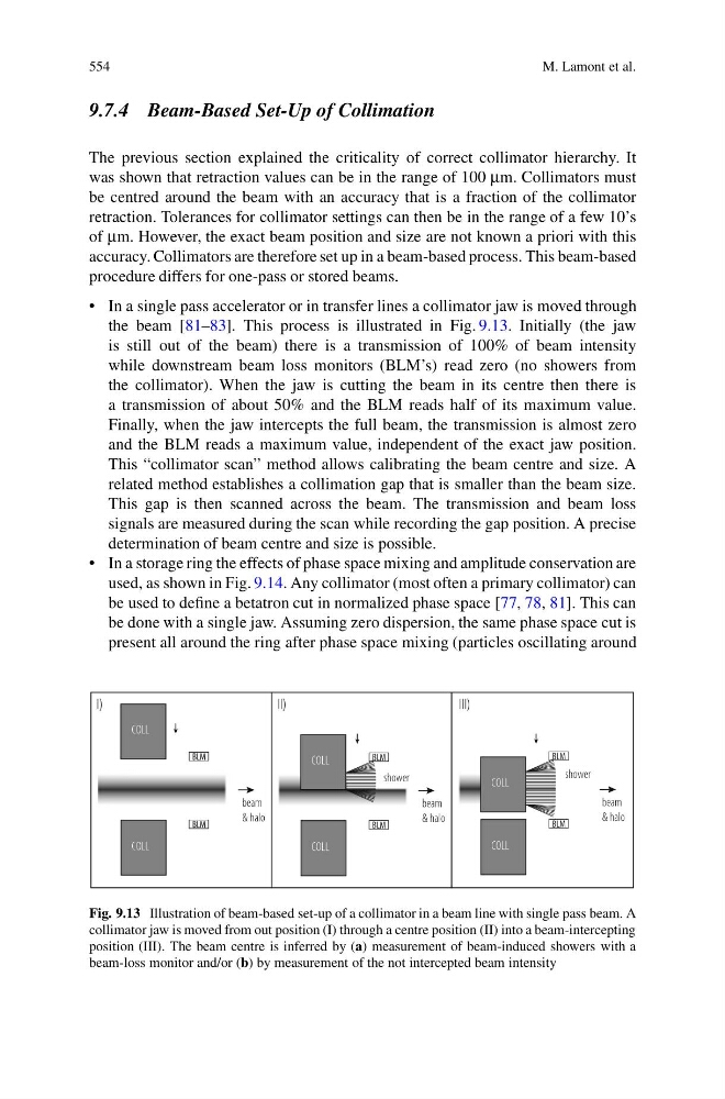
the beam [81–83]. This process is illustrated in Fig. 9.13. Initially (the jaw
is still out of the beam) there is a transmission of 100% of beam intensity
while downstream beam loss monitors (BLM’s) read zero (no showers from
the collimator). When the jaw is cutting the beam in its centre then there is
a transmission of about 50% and the BLM reads half of its maximum value.
Finally, when the jaw intercepts the full beam, the transmission is almost zero
and the BLM reads a maximum value, independent of the exact jaw position.
This “collimator scan” method allows calibrating the beam centre and size. A
related method establishes a collimation gap that is smaller than the beam size.
This gap is then scanned across the beam. The transmission and beam loss
signals are measured during the scan while recording the gap position. A precise
determination of beam centre and size is possible.
• In a storage ring the effects of phase space mixing and amplitude conservation are
used, as shown in Fig. 9.14. Any collimator (most often a primary collimator) can
be used to define a betatron cut in normalized phase space [77, 78, 81]. This can
be done with a single jaw. Assuming zero dispersion, the same phase space cut is
present all around the ring after phase space mixing (particles oscillating around
BLM
COLL
beam
& halo
COLL
BLM
BLM
COLL
beam
& halo
COLL
BLM
BLM
COLL
beam
& halo
COLL
BLM
I)
II)
III)
shower
shower
Fig. 9.13 Illustration of beam-based set-up of a collimator in a beam line with single pass beam. A
collimator jaw is moved from out position (I) through a centre position (II) into a beam-intercepting
position (III). The beam centre is inferred by (a) measurement of beam-induced showers with a
beam-loss monitor and/or (b) by measurement of the not intercepted beam intensity
M. Lamont et al.
9.7.4 Beam-Based Set-Up of Collimation
The previous section explained the criticality of correct collimator hierarchy. It
was shown that retraction values can be in the range of 100 μm. Collimators must
be centred around the beam with an accuracy that is a fraction of the collimator
retraction. Tolerances for collimator settings can then be in the range of a few 10’s
of μm. However, the exact beam position and size are not known a priori with this
accuracy. Collimators are therefore set up in a beam-based process. This beam-based
procedure differs for one-pass or stored beams.
• In a single pass accelerator or in transfer lines a collimator jaw is moved through
the beam [81–83]. This process is illustrated in Fig. 9.13. Initially (the jaw
is still out of the beam) there is a transmission of 100% of beam intensity
while downstream beam loss monitors (BLM’s) read zero (no showers from
the collimator). When the jaw is cutting the beam in its centre then there is
a transmission of about 50% and the BLM reads half of its maximum value.
Finally, when the jaw intercepts the full beam, the transmission is almost zero
and the BLM reads a maximum value, independent of the exact jaw position.
This “collimator scan” method allows calibrating the beam centre and size. A
related method establishes a collimation gap that is smaller than the beam size.
This gap is then scanned across the beam. The transmission and beam loss
signals are measured during the scan while recording the gap position. A precise
determination of beam centre and size is possible.
• In a storage ring the effects of phase space mixing and amplitude conservation are
used, as shown in Fig. 9.14. Any collimator (most often a primary collimator) can
be used to define a betatron cut in normalized phase space [77, 78, 81]. This can
be done with a single jaw. Assuming zero dispersion, the same phase space cut is
present all around the ring after phase space mixing (particles oscillating around
BLM
COLL
beam
& halo
COLL
BLM
BLM
COLL
beam
& halo
COLL
BLM
BLM
COLL
beam
& halo
COLL
BLM
I)
II)
III)
shower
shower
Fig. 9.13 Illustration of beam-based set-up of a collimator in a beam line with single pass beam. A
collimator jaw is moved from out position (I) through a centre position (II) into a beam-intercepting
position (III). The beam centre is inferred by (a) measurement of beam-induced showers with a
beam-loss monitor and/or (b) by measurement of the not intercepted beam intensity