

9 Accelerator Operations
543
parameters. The area occupied in the longitudinal phase plane (emittance) remaining
constant, bunch length l b (in ns) and energy spread b (in eV) evolve like:
l b ∝
1
β
·
η
γ · hV cos ϕ s
1
4
,
(9.54)
b ∝ β ·
γ · hV cos ϕ s
η
1
4
.
(9.55)
When the accelerator parameters (e.g. RF voltage or phase) are quickly varying,
the process is non-adiabatic and tracking simulations are required to evaluate the
final particle distribution. Although the local density of particles remains constant,
the contour containing all particles is usually not a stable trajectory in the final
state and the resulting emittance is therefore larger because of filamentation. Nonadiabatic beam manipulations allow getting bunch lengths and energy spreads
which cannot be obtained with adiabatic processes (“bunch rotation”). They also
give the possibility to blow-up the longitudinal emittance in a controlled fashion
(“longitudinal controlled blow-up”).
9.6.3 Bunch Rotation
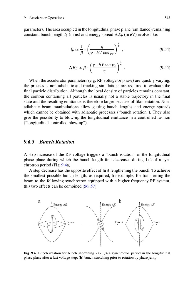
A step increase of the RF voltage triggers a “bunch rotation” in the longitudinal
phase plane during which the bunch length first decreases during 1/4 of a synchrotron period (Fig. 9.4a).
A step decrease has the opposite effect of first lengthening the bunch. To achieve
the smallest possible bunch length, as required, for example, for transferring the
beam to the following synchrotron equipped with a higher frequency RF system,
this two effects can be combined [56, 57].
Fig. 9.4 Bunch rotation for bunch shortening. (a) 1/4 a synchrotron period in the longitudinal
phase plane after a fast voltage step; (b) bunch stretching prior to rotation by phase jump
543
parameters. The area occupied in the longitudinal phase plane (emittance) remaining
constant, bunch length l b (in ns) and energy spread b (in eV) evolve like:
l b ∝
1
β
·
η
γ · hV cos ϕ s
1
4
,
(9.54)
b ∝ β ·
γ · hV cos ϕ s
η
1
4
.
(9.55)
When the accelerator parameters (e.g. RF voltage or phase) are quickly varying,
the process is non-adiabatic and tracking simulations are required to evaluate the
final particle distribution. Although the local density of particles remains constant,
the contour containing all particles is usually not a stable trajectory in the final
state and the resulting emittance is therefore larger because of filamentation. Nonadiabatic beam manipulations allow getting bunch lengths and energy spreads
which cannot be obtained with adiabatic processes (“bunch rotation”). They also
give the possibility to blow-up the longitudinal emittance in a controlled fashion
(“longitudinal controlled blow-up”).
9.6.3 Bunch Rotation
A step increase of the RF voltage triggers a “bunch rotation” in the longitudinal
phase plane during which the bunch length first decreases during 1/4 of a synchrotron period (Fig. 9.4a).
A step decrease has the opposite effect of first lengthening the bunch. To achieve
the smallest possible bunch length, as required, for example, for transferring the
beam to the following synchrotron equipped with a higher frequency RF system,
this two effects can be combined [56, 57].
Fig. 9.4 Bunch rotation for bunch shortening. (a) 1/4 a synchrotron period in the longitudinal
phase plane after a fast voltage step; (b) bunch stretching prior to rotation by phase jump