

8 Accelerator Engineering and Technology: Accelerator Technology
481
Primary stage
(low Z)
Secondary
stage (low Z)
SC triplet
Primary
beam &
halo
Se co nd ary ha lo
Ter tia ry hal o
Cleaning insertion
Experimental insertion
Tertiary stage
(high Z)
Qu ar tia ry ha lo
n 1
n 2
n 3
n 4
Absorbing
stage (high Z)
SC arc(s)
Beam
orbit
n arc (γ)
n triplet (β
* )
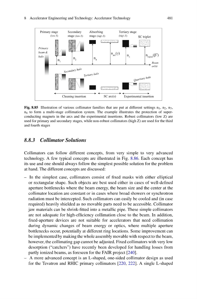
Fig. 8.85 Illustration of various collimator families that are put at different settings n 1 , n 2 , n 3 ,
n 4 to form a multi-stage collimation system. The example illustrates the protection of superconducting magnets in the arcs and the experimental insertions. Robust collimators (low Z) are
used for primary and secondary stages, while non-robust collimators (high Z) are used for the third
and fourth stages
8.8.3 Collimator Solutions
Collimators can follow different concepts, from very simple to very advanced
technology. A few typical concepts are illustrated in Fig. 8.86. Each concept has
its use and one should always follow the simplest possible solution for the problem
at hand. The different concepts are discussed:
– In the simplest case, collimators consist of fixed masks with either elliptical
or rectangular shape. Such objects are best used either in cases of well-defined
aperture bottlenecks where the beam energy, the beam size and the center at the
collimator location are constant or in cases where broad showers or synchrotron
radiation must be intercepted. Such collimators can easily be cooled and (in case
required) heavily shielded as no movable parts need to be accessible. Collimator
jaw materials can be shrink-fitted into a metallic pipe. These simple collimators
are not adequate for high-efficiency collimation close to the beam. In addition,
fixed-aperture devices are not suitable for accelerators that need collimation
during dynamic changes of beam energy or optics, where multiple aperture
bottlenecks occur, potentially at different ring locations. Some improvement can
be implemented by making the whole assembly movable with respect to the beam,
however, the collimating gap cannot be adjusted. Fixed collimators with very low
desorption (“catchers”) have recently been developed for handling losses from
partly ionized beams, as foreseen for the FAIR project [240].
– A more advanced concept is an L-shaped, one-sided collimator design as used
for the Tevatron and RHIC primary collimators [220, 222]. A single L-shaped
481
Primary stage
(low Z)
Secondary
stage (low Z)
SC triplet
Primary
beam &
halo
Se co nd ary ha lo
Ter tia ry hal o
Cleaning insertion
Experimental insertion
Tertiary stage
(high Z)
Qu ar tia ry ha lo
n 1
n 2
n 3
n 4
Absorbing
stage (high Z)
SC arc(s)
Beam
orbit
n arc (γ)
n triplet (β
* )
Fig. 8.85 Illustration of various collimator families that are put at different settings n 1 , n 2 , n 3 ,
n 4 to form a multi-stage collimation system. The example illustrates the protection of superconducting magnets in the arcs and the experimental insertions. Robust collimators (low Z) are
used for primary and secondary stages, while non-robust collimators (high Z) are used for the third
and fourth stages
8.8.3 Collimator Solutions
Collimators can follow different concepts, from very simple to very advanced
technology. A few typical concepts are illustrated in Fig. 8.86. Each concept has
its use and one should always follow the simplest possible solution for the problem
at hand. The different concepts are discussed:
– In the simplest case, collimators consist of fixed masks with either elliptical
or rectangular shape. Such objects are best used either in cases of well-defined
aperture bottlenecks where the beam energy, the beam size and the center at the
collimator location are constant or in cases where broad showers or synchrotron
radiation must be intercepted. Such collimators can easily be cooled and (in case
required) heavily shielded as no movable parts need to be accessible. Collimator
jaw materials can be shrink-fitted into a metallic pipe. These simple collimators
are not adequate for high-efficiency collimation close to the beam. In addition,
fixed-aperture devices are not suitable for accelerators that need collimation
during dynamic changes of beam energy or optics, where multiple aperture
bottlenecks occur, potentially at different ring locations. Some improvement can
be implemented by making the whole assembly movable with respect to the beam,
however, the collimating gap cannot be adjusted. Fixed collimators with very low
desorption (“catchers”) have recently been developed for handling losses from
partly ionized beams, as foreseen for the FAIR project [240].
– A more advanced concept is an L-shaped, one-sided collimator design as used
for the Tevatron and RHIC primary collimators [220, 222]. A single L-shaped