

472
F. Bordry et al.
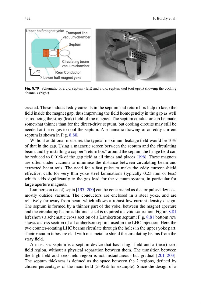
Fig. 8.79 Schematic of a d.c. septum (left) and a d.c. septum coil (cut open) showing the cooling
channels (right)
created. These induced eddy currents in the septum and return box help to keep the
field inside the magnet gap, thus improving the field homogeneity in the gap as well
as reducing the stray (leak) field of the magnet. The septum conductor can be made
somewhat thinner than for the direct-drive septum, but cooling circuits may still be
needed at the edges to cool the septum. A schematic drawing of an eddy-current
septum is shown in Fig. 8.80.
Without additional measures the typical maximum leakage field would be 10%
of that in the gap. Using a magnetic screen between the septum and the circulating
beam, and by installing a copper “return box” around the septum the fringe field can
be reduced to 0.01% of the gap field at all times and places [196]. These magnets
are often under vacuum to minimise the distance between circulating beam and
extracted beam axis. The need for a fast pulse to make the eddy current shield
effective, calls for very thin yoke steel laminations (typically 0.23 mm or less)
which adds significantly to the gas load for the vacuum system, in particular for
large aperture magnets.
Lambertson (steel) septa [197–200] can be constructed as d.c. or pulsed devices,
mostly outside vacuum. The conductors are enclosed in a steel yoke, and are
relatively far away from beam which allows a robust low current density design.
The septum is formed by a thinner part of the yoke, between the magnet aperture
and the circulating beam; additional steel is required to avoid saturation. Figure 8.81
left shows a schematic cross section of a Lambertson septum; Fig. 8.81 bottom row
shows a cross section of a Lambertson septum used in the LHC injection. Here the
two counter-rotating LHC beams circulate through the holes in the upper yoke part.
Their vacuum tubes are clad with mu-metal to shield the circulating beams from the
stray field.
A massless septum is a septum device that has a high field and a (near) zero
field region, without a physical separation between them. The transition between
the high field and zero field region is not instantaneous but gradual [201–203].
The septum thickness is defined as the space between the 2 regions, defined by
chosen percentages of the main field (5–95% for example). Since the design of a
F. Bordry et al.
Fig. 8.79 Schematic of a d.c. septum (left) and a d.c. septum coil (cut open) showing the cooling
channels (right)
created. These induced eddy currents in the septum and return box help to keep the
field inside the magnet gap, thus improving the field homogeneity in the gap as well
as reducing the stray (leak) field of the magnet. The septum conductor can be made
somewhat thinner than for the direct-drive septum, but cooling circuits may still be
needed at the edges to cool the septum. A schematic drawing of an eddy-current
septum is shown in Fig. 8.80.
Without additional measures the typical maximum leakage field would be 10%
of that in the gap. Using a magnetic screen between the septum and the circulating
beam, and by installing a copper “return box” around the septum the fringe field can
be reduced to 0.01% of the gap field at all times and places [196]. These magnets
are often under vacuum to minimise the distance between circulating beam and
extracted beam axis. The need for a fast pulse to make the eddy current shield
effective, calls for very thin yoke steel laminations (typically 0.23 mm or less)
which adds significantly to the gas load for the vacuum system, in particular for
large aperture magnets.
Lambertson (steel) septa [197–200] can be constructed as d.c. or pulsed devices,
mostly outside vacuum. The conductors are enclosed in a steel yoke, and are
relatively far away from beam which allows a robust low current density design.
The septum is formed by a thinner part of the yoke, between the magnet aperture
and the circulating beam; additional steel is required to avoid saturation. Figure 8.81
left shows a schematic cross section of a Lambertson septum; Fig. 8.81 bottom row
shows a cross section of a Lambertson septum used in the LHC injection. Here the
two counter-rotating LHC beams circulate through the holes in the upper yoke part.
Their vacuum tubes are clad with mu-metal to shield the circulating beams from the
stray field.
A massless septum is a septum device that has a high field and a (near) zero
field region, without a physical separation between them. The transition between
the high field and zero field region is not instantaneous but gradual [201–203].
The septum thickness is defined as the space between the 2 regions, defined by
chosen percentages of the main field (5–95% for example). Since the design of a