

470
F. Bordry et al.
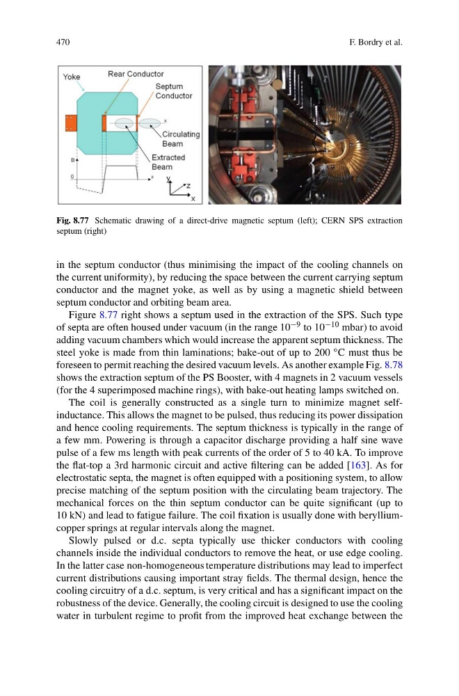
Fig. 8.77 Schematic drawing of a direct-drive magnetic septum (left); CERN SPS extraction
septum (right)
in the septum conductor (thus minimising the impact of the cooling channels on
the current uniformity), by reducing the space between the current carrying septum
conductor and the magnet yoke, as well as by using a magnetic shield between
septum conductor and orbiting beam area.
Figure 8.77 right shows a septum used in the extraction of the SPS. Such type
of septa are often housed under vacuum (in the range 10 −9 to 10 −10 mbar) to avoid
adding vacuum chambers which would increase the apparent septum thickness. The
steel yoke is made from thin laminations; bake-out of up to 200 ◦ C must thus be
foreseen to permit reaching the desired vacuum levels. As another example Fig. 8.78
shows the extraction septum of the PS Booster, with 4 magnets in 2 vacuum vessels
(for the 4 superimposed machine rings), with bake-out heating lamps switched on.
The coil is generally constructed as a single turn to minimize magnet selfinductance. This allows the magnet to be pulsed, thus reducing its power dissipation
and hence cooling requirements. The septum thickness is typically in the range of
a few mm. Powering is through a capacitor discharge providing a half sine wave
pulse of a few ms length with peak currents of the order of 5 to 40 kA. To improve
the flat-top a 3rd harmonic circuit and active filtering can be added [163]. As for
electrostatic septa, the magnet is often equipped with a positioning system, to allow
precise matching of the septum position with the circulating beam trajectory. The
mechanical forces on the thin septum conductor can be quite significant (up to
10 kN) and lead to fatigue failure. The coil fixation is usually done with berylliumcopper springs at regular intervals along the magnet.
Slowly pulsed or d.c. septa typically use thicker conductors with cooling
channels inside the individual conductors to remove the heat, or use edge cooling.
In the latter case non-homogeneous temperature distributions may lead to imperfect
current distributions causing important stray fields. The thermal design, hence the
cooling circuitry of a d.c. septum, is very critical and has a significant impact on the
robustness of the device. Generally, the cooling circuit is designed to use the cooling
water in turbulent regime to profit from the improved heat exchange between the
F. Bordry et al.
Fig. 8.77 Schematic drawing of a direct-drive magnetic septum (left); CERN SPS extraction
septum (right)
in the septum conductor (thus minimising the impact of the cooling channels on
the current uniformity), by reducing the space between the current carrying septum
conductor and the magnet yoke, as well as by using a magnetic shield between
septum conductor and orbiting beam area.
Figure 8.77 right shows a septum used in the extraction of the SPS. Such type
of septa are often housed under vacuum (in the range 10 −9 to 10 −10 mbar) to avoid
adding vacuum chambers which would increase the apparent septum thickness. The
steel yoke is made from thin laminations; bake-out of up to 200 ◦ C must thus be
foreseen to permit reaching the desired vacuum levels. As another example Fig. 8.78
shows the extraction septum of the PS Booster, with 4 magnets in 2 vacuum vessels
(for the 4 superimposed machine rings), with bake-out heating lamps switched on.
The coil is generally constructed as a single turn to minimize magnet selfinductance. This allows the magnet to be pulsed, thus reducing its power dissipation
and hence cooling requirements. The septum thickness is typically in the range of
a few mm. Powering is through a capacitor discharge providing a half sine wave
pulse of a few ms length with peak currents of the order of 5 to 40 kA. To improve
the flat-top a 3rd harmonic circuit and active filtering can be added [163]. As for
electrostatic septa, the magnet is often equipped with a positioning system, to allow
precise matching of the septum position with the circulating beam trajectory. The
mechanical forces on the thin septum conductor can be quite significant (up to
10 kN) and lead to fatigue failure. The coil fixation is usually done with berylliumcopper springs at regular intervals along the magnet.
Slowly pulsed or d.c. septa typically use thicker conductors with cooling
channels inside the individual conductors to remove the heat, or use edge cooling.
In the latter case non-homogeneous temperature distributions may lead to imperfect
current distributions causing important stray fields. The thermal design, hence the
cooling circuitry of a d.c. septum, is very critical and has a significant impact on the
robustness of the device. Generally, the cooling circuit is designed to use the cooling
water in turbulent regime to profit from the improved heat exchange between the