

458
F. Bordry et al.
be reduced. An additional “clipper switch” can be used to connect the magnet side
of the PFN to ground in order to improve the fall time. The main components of
the electrical circuit are all matched to a characteristic impedance Z (typically in
the range of a few Ohms to a few tens of Ohms) to avoid unwanted reflections
and thus distortions of the pulse shape. The interplay of the different components
is therefore important and a carefully chosen set of parameters and a coherent
design are required to achieve optimum performance. Computer aided design tools
(electric circuit simulation and finite element analysis software) are used extensively
to predict and verify the performance achieved by the hardware, or to study how an
existing system can be improved [162]. The main components of a kicker system
are presented in more detail below.
8.7.1.1 Kicker Magnets
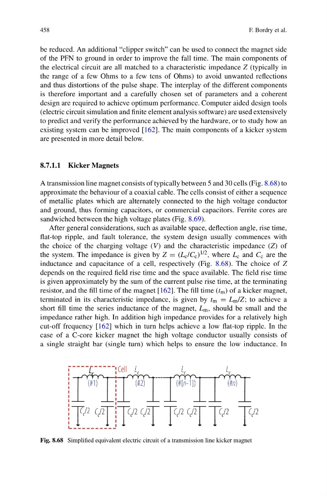
A transmission line magnet consists of typically between 5 and 30 cells (Fig. 8.68) to
approximate the behaviour of a coaxial cable. The cells consist of either a sequence
of metallic plates which are alternately connected to the high voltage conductor
and ground, thus forming capacitors, or commercial capacitors. Ferrite cores are
sandwiched between the high voltage plates (Fig. 8.69).
After general considerations, such as available space, deflection angle, rise time,
flat-top ripple, and fault tolerance, the system design usually commences with
the choice of the charging voltage (V) and the characteristic impedance (Z) of
the system. The impedance is given by Z = (L c /C c ) 1/2 , where L c and C c are the
inductance and capacitance of a cell, respectively (Fig. 8.68). The choice of Z
depends on the required field rise time and the space available. The field rise time
is given approximately by the sum of the current pulse rise time, at the terminating
resistor, and the fill time of the magnet [162]. The fill time (t m ) of a kicker magnet,
terminated in its characteristic impedance, is given by t m = L m /Z; to achieve a
short fill time the series inductance of the magnet, L m , should be small and the
impedance rather high. In addition high impedance provides for a relatively high
cut-off frequency [162] which in turn helps achieve a low flat-top ripple. In the
case of a C-core kicker magnet the high voltage conductor usually consists of
a single straight bar (single turn) which helps to ensure the low inductance. In
Fig. 8.68 Simplified equivalent electric circuit of a transmission line kicker magnet
F. Bordry et al.
be reduced. An additional “clipper switch” can be used to connect the magnet side
of the PFN to ground in order to improve the fall time. The main components of
the electrical circuit are all matched to a characteristic impedance Z (typically in
the range of a few Ohms to a few tens of Ohms) to avoid unwanted reflections
and thus distortions of the pulse shape. The interplay of the different components
is therefore important and a carefully chosen set of parameters and a coherent
design are required to achieve optimum performance. Computer aided design tools
(electric circuit simulation and finite element analysis software) are used extensively
to predict and verify the performance achieved by the hardware, or to study how an
existing system can be improved [162]. The main components of a kicker system
are presented in more detail below.
8.7.1.1 Kicker Magnets
A transmission line magnet consists of typically between 5 and 30 cells (Fig. 8.68) to
approximate the behaviour of a coaxial cable. The cells consist of either a sequence
of metallic plates which are alternately connected to the high voltage conductor
and ground, thus forming capacitors, or commercial capacitors. Ferrite cores are
sandwiched between the high voltage plates (Fig. 8.69).
After general considerations, such as available space, deflection angle, rise time,
flat-top ripple, and fault tolerance, the system design usually commences with
the choice of the charging voltage (V) and the characteristic impedance (Z) of
the system. The impedance is given by Z = (L c /C c ) 1/2 , where L c and C c are the
inductance and capacitance of a cell, respectively (Fig. 8.68). The choice of Z
depends on the required field rise time and the space available. The field rise time
is given approximately by the sum of the current pulse rise time, at the terminating
resistor, and the fill time of the magnet [162]. The fill time (t m ) of a kicker magnet,
terminated in its characteristic impedance, is given by t m = L m /Z; to achieve a
short fill time the series inductance of the magnet, L m , should be small and the
impedance rather high. In addition high impedance provides for a relatively high
cut-off frequency [162] which in turn helps achieve a low flat-top ripple. In the
case of a C-core kicker magnet the high voltage conductor usually consists of
a single straight bar (single turn) which helps to ensure the low inductance. In
Fig. 8.68 Simplified equivalent electric circuit of a transmission line kicker magnet