

8 Accelerator Engineering and Technology: Accelerator Technology
457
can track current rise to within ~1 ns [165], while slower kickers can use laminated
steel yokes. Fast rise times are particularly required in smaller machines to optimize
the filling factor (amount of beam which can be injected). Useable pulse durations
are in the range of a few 100 ns to 100 μs (case of the CERN LHC beam dump
kicker which must empty the whole 27 km circumference at once; here the fall time
is not important as all beam is anyway extracted after one turn). Even faster rise
times, in the range of a few ns, can be achieved with yoke-free stripline kickers,
where the field is created by a pulse running along two longitudinal electrodes [166,
167].
The main design options for kicker systems include the type of magnet (“travelling wave” (also known as “transmission line”) or “lumped inductance”), the
installation of the magnet in- or outside of the machine vacuum, the type of aperture
(window-frame or C-core), and the type of termination (impedance-matched or
short-circuited) [162]. The actual choice depends on the demands and constraints
of the application, but is also impacted by cost considerations. Applications where
a considerable number of bunches must be placed at a precise position on the
circumference of an accelerator, without disturbing the already circulating bunches,
or where only a part of the circulating beam needs to be extracted, requires kickers
with fast rise and fall time. Low flat-top ripple reduces the injection oscillations
which could lead to emittance blow-up (in hadron machines), and ensures constant
deflection angle for a train of extracted bunches. To achieve fast rise and fall times
and low flat-top ripple, quasi-rectangular pulses are applied to “transmission line”
kicker magnets. For space reasons most of the discussion below will be devoted to
such systems.
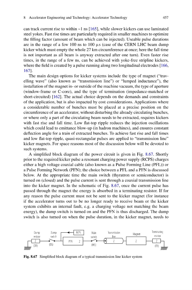
A simplified block diagram of the power circuit is given in Fig. 8.67. Shortly
prior to the required kicker pulse a resonant charging power supply (RCPS) charges
either a high voltage coaxial cable (also known as a Pulse Forming Line (PFL)) or
a Pulse Forming Network (PFN); the choice between a PFL and a PFN is discussed
below. At the appropriate time the main switch (thyratron or semiconductor) is
turned on (closed) and the pulse current is sent through a coaxial transmission line
into the kicker magnet. In the schematic of Fig. 8.67, once the current pulse has
passed through the magnet the energy is absorbed in a terminating resistor. If for
any reason the pulse current must not be sent to the kicker magnet (for instance
if the accelerator turns out to be no longer ready to receive beam or the kicker
system exhibits an internal fault, e.g. a charging voltage not matching the beam
energy), the dump switch is turned on and the PFN is thus discharged. The dump
switch is also turned on when the pulse duration, in the kicker magnet, needs to
Fig. 8.67 Simplified block diagram of a typical transmission line kicker system
457
can track current rise to within ~1 ns [165], while slower kickers can use laminated
steel yokes. Fast rise times are particularly required in smaller machines to optimize
the filling factor (amount of beam which can be injected). Useable pulse durations
are in the range of a few 100 ns to 100 μs (case of the CERN LHC beam dump
kicker which must empty the whole 27 km circumference at once; here the fall time
is not important as all beam is anyway extracted after one turn). Even faster rise
times, in the range of a few ns, can be achieved with yoke-free stripline kickers,
where the field is created by a pulse running along two longitudinal electrodes [166,
167].
The main design options for kicker systems include the type of magnet (“travelling wave” (also known as “transmission line”) or “lumped inductance”), the
installation of the magnet in- or outside of the machine vacuum, the type of aperture
(window-frame or C-core), and the type of termination (impedance-matched or
short-circuited) [162]. The actual choice depends on the demands and constraints
of the application, but is also impacted by cost considerations. Applications where
a considerable number of bunches must be placed at a precise position on the
circumference of an accelerator, without disturbing the already circulating bunches,
or where only a part of the circulating beam needs to be extracted, requires kickers
with fast rise and fall time. Low flat-top ripple reduces the injection oscillations
which could lead to emittance blow-up (in hadron machines), and ensures constant
deflection angle for a train of extracted bunches. To achieve fast rise and fall times
and low flat-top ripple, quasi-rectangular pulses are applied to “transmission line”
kicker magnets. For space reasons most of the discussion below will be devoted to
such systems.
A simplified block diagram of the power circuit is given in Fig. 8.67. Shortly
prior to the required kicker pulse a resonant charging power supply (RCPS) charges
either a high voltage coaxial cable (also known as a Pulse Forming Line (PFL)) or
a Pulse Forming Network (PFN); the choice between a PFL and a PFN is discussed
below. At the appropriate time the main switch (thyratron or semiconductor) is
turned on (closed) and the pulse current is sent through a coaxial transmission line
into the kicker magnet. In the schematic of Fig. 8.67, once the current pulse has
passed through the magnet the energy is absorbed in a terminating resistor. If for
any reason the pulse current must not be sent to the kicker magnet (for instance
if the accelerator turns out to be no longer ready to receive beam or the kicker
system exhibits an internal fault, e.g. a charging voltage not matching the beam
energy), the dump switch is turned on and the PFN is thus discharged. The dump
switch is also turned on when the pulse duration, in the kicker magnet, needs to
Fig. 8.67 Simplified block diagram of a typical transmission line kicker system