

8 Accelerator Engineering and Technology: Accelerator Technology
409
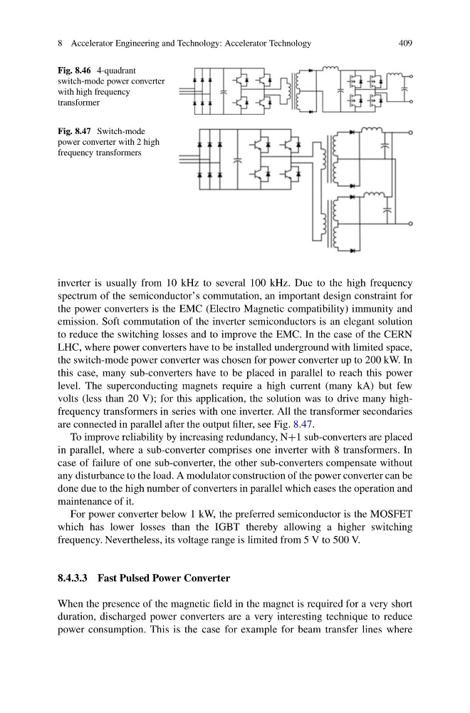
Fig. 8.46 4-quadrant
switch-mode power converter
with high frequency
transformer
Fig. 8.47 Switch-mode
power converter with 2 high
frequency transformers
inverter is usually from 10 kHz to several 100 kHz. Due to the high frequency
spectrum of the semiconductor’s commutation, an important design constraint for
the power converters is the EMC (Electro Magnetic compatibility) immunity and
emission. Soft commutation of the inverter semiconductors is an elegant solution
to reduce the switching losses and to improve the EMC. In the case of the CERN
LHC, where power converters have to be installed underground with limited space,
the switch-mode power converter was chosen for power converter up to 200 kW. In
this case, many sub-converters have to be placed in parallel to reach this power
level. The superconducting magnets require a high current (many kA) but few
volts (less than 20 V); for this application, the solution was to drive many highfrequency transformers in series with one inverter. All the transformer secondaries
are connected in parallel after the output filter, see Fig. 8.47.
To improve reliability by increasing redundancy, N+1 sub-converters are placed
in parallel, where a sub-converter comprises one inverter with 8 transformers. In
case of failure of one sub-converter, the other sub-converters compensate without
any disturbance to the load. A modulator construction of the power converter can be
done due to the high number of converters in parallel which eases the operation and
maintenance of it.
For power converter below 1 kW, the preferred semiconductor is the MOSFET
which has lower losses than the IGBT thereby allowing a higher switching
frequency. Nevertheless, its voltage range is limited from 5 V to 500 V.
8.4.3.3 Fast Pulsed Power Converter
When the presence of the magnetic field in the magnet is required for a very short
duration, discharged power converters are a very interesting technique to reduce
power consumption. This is the case for example for beam transfer lines where
409
Fig. 8.46 4-quadrant
switch-mode power converter
with high frequency
transformer
Fig. 8.47 Switch-mode
power converter with 2 high
frequency transformers
inverter is usually from 10 kHz to several 100 kHz. Due to the high frequency
spectrum of the semiconductor’s commutation, an important design constraint for
the power converters is the EMC (Electro Magnetic compatibility) immunity and
emission. Soft commutation of the inverter semiconductors is an elegant solution
to reduce the switching losses and to improve the EMC. In the case of the CERN
LHC, where power converters have to be installed underground with limited space,
the switch-mode power converter was chosen for power converter up to 200 kW. In
this case, many sub-converters have to be placed in parallel to reach this power
level. The superconducting magnets require a high current (many kA) but few
volts (less than 20 V); for this application, the solution was to drive many highfrequency transformers in series with one inverter. All the transformer secondaries
are connected in parallel after the output filter, see Fig. 8.47.
To improve reliability by increasing redundancy, N+1 sub-converters are placed
in parallel, where a sub-converter comprises one inverter with 8 transformers. In
case of failure of one sub-converter, the other sub-converters compensate without
any disturbance to the load. A modulator construction of the power converter can be
done due to the high number of converters in parallel which eases the operation and
maintenance of it.
For power converter below 1 kW, the preferred semiconductor is the MOSFET
which has lower losses than the IGBT thereby allowing a higher switching
frequency. Nevertheless, its voltage range is limited from 5 V to 500 V.
8.4.3.3 Fast Pulsed Power Converter
When the presence of the magnetic field in the magnet is required for a very short
duration, discharged power converters are a very interesting technique to reduce
power consumption. This is the case for example for beam transfer lines where