

408
F. Bordry et al.
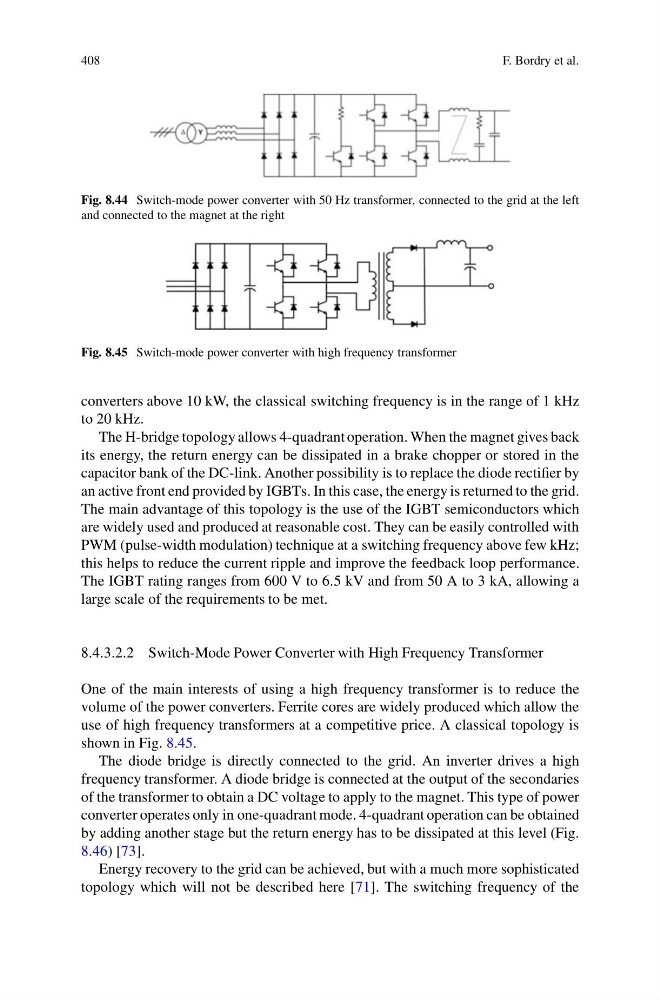
Fig. 8.44 Switch-mode power converter with 50 Hz transformer, connected to the grid at the left
and connected to the magnet at the right
Fig. 8.45 Switch-mode power converter with high frequency transformer
converters above 10 kW, the classical switching frequency is in the range of 1 kHz
to 20 kHz.
The H-bridge topology allows 4-quadrant operation. When the magnet gives back
its energy, the return energy can be dissipated in a brake chopper or stored in the
capacitor bank of the DC-link. Another possibility is to replace the diode rectifier by
an active front end provided by IGBTs. In this case, the energy is returned to the grid.
The main advantage of this topology is the use of the IGBT semiconductors which
are widely used and produced at reasonable cost. They can be easily controlled with
PWM (pulse-width modulation) technique at a switching frequency above few kHz;
this helps to reduce the current ripple and improve the feedback loop performance.
The IGBT rating ranges from 600 V to 6.5 kV and from 50 A to 3 kA, allowing a
large scale of the requirements to be met.
8.4.3.2.2 Switch-Mode Power Converter with High Frequency Transformer
One of the main interests of using a high frequency transformer is to reduce the
volume of the power converters. Ferrite cores are widely produced which allow the
use of high frequency transformers at a competitive price. A classical topology is
shown in Fig. 8.45.
The diode bridge is directly connected to the grid. An inverter drives a high
frequency transformer. A diode bridge is connected at the output of the secondaries
of the transformer to obtain a DC voltage to apply to the magnet. This type of power
converter operates only in one-quadrant mode. 4-quadrant operation can be obtained
by adding another stage but the return energy has to be dissipated at this level (Fig.
8.46) [73].
Energy recovery to the grid can be achieved, but with a much more sophisticated
topology which will not be described here [71]. The switching frequency of the
F. Bordry et al.
Fig. 8.44 Switch-mode power converter with 50 Hz transformer, connected to the grid at the left
and connected to the magnet at the right
Fig. 8.45 Switch-mode power converter with high frequency transformer
converters above 10 kW, the classical switching frequency is in the range of 1 kHz
to 20 kHz.
The H-bridge topology allows 4-quadrant operation. When the magnet gives back
its energy, the return energy can be dissipated in a brake chopper or stored in the
capacitor bank of the DC-link. Another possibility is to replace the diode rectifier by
an active front end provided by IGBTs. In this case, the energy is returned to the grid.
The main advantage of this topology is the use of the IGBT semiconductors which
are widely used and produced at reasonable cost. They can be easily controlled with
PWM (pulse-width modulation) technique at a switching frequency above few kHz;
this helps to reduce the current ripple and improve the feedback loop performance.
The IGBT rating ranges from 600 V to 6.5 kV and from 50 A to 3 kA, allowing a
large scale of the requirements to be met.
8.4.3.2.2 Switch-Mode Power Converter with High Frequency Transformer
One of the main interests of using a high frequency transformer is to reduce the
volume of the power converters. Ferrite cores are widely produced which allow the
use of high frequency transformers at a competitive price. A classical topology is
shown in Fig. 8.45.
The diode bridge is directly connected to the grid. An inverter drives a high
frequency transformer. A diode bridge is connected at the output of the secondaries
of the transformer to obtain a DC voltage to apply to the magnet. This type of power
converter operates only in one-quadrant mode. 4-quadrant operation can be obtained
by adding another stage but the return energy has to be dissipated at this level (Fig.
8.46) [73].
Energy recovery to the grid can be achieved, but with a much more sophisticated
topology which will not be described here [71]. The switching frequency of the