

8 Accelerator Engineering and Technology: Accelerator Technology
407
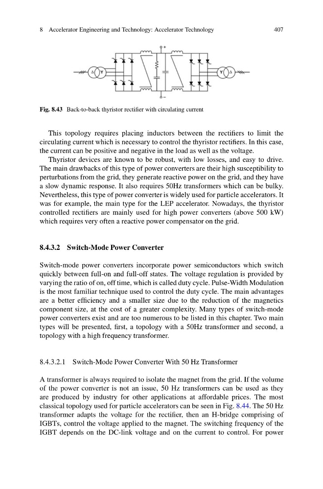
Fig. 8.43 Back-to-back thyristor rectifier with circulating current
This topology requires placing inductors between the rectifiers to limit the
circulating current which is necessary to control the thyristor rectifiers. In this case,
the current can be positive and negative in the load as well as the voltage.
Thyristor devices are known to be robust, with low losses, and easy to drive.
The main drawbacks of this type of power converters are their high susceptibility to
perturbations from the grid, they generate reactive power on the grid, and they have
a slow dynamic response. It also requires 50Hz transformers which can be bulky.
Nevertheless, this type of power converter is widely used for particle accelerators. It
was for example, the main type for the LEP accelerator. Nowadays, the thyristor
controlled rectifiers are mainly used for high power converters (above 500 kW)
which requires very often a reactive power compensator on the grid.
8.4.3.2 Switch-Mode Power Converter
Switch-mode power converters incorporate power semiconductors which switch
quickly between full-on and full-off states. The voltage regulation is provided by
varying the ratio of on, off time, which is called duty cycle. Pulse-Width Modulation
is the most familiar technique used to control the duty cycle. The main advantages
are a better efficiency and a smaller size due to the reduction of the magnetics
component size, at the cost of a greater complexity. Many types of switch-mode
power converters exist and are too numerous to be listed in this chapter. Two main
types will be presented, first, a topology with a 50Hz transformer and second, a
topology with a high frequency transformer.
8.4.3.2.1 Switch-Mode Power Converter With 50 Hz Transformer
A transformer is always required to isolate the magnet from the grid. If the volume
of the power converter is not an issue, 50 Hz transformers can be used as they
are produced by industry for other applications at affordable prices. The most
classical topology used for particle accelerators can be seen in Fig. 8.44. The 50 Hz
transformer adapts the voltage for the rectifier, then an H-bridge comprising of
IGBTs, control the voltage applied to the magnet. The switching frequency of the
IGBT depends on the DC-link voltage and on the current to control. For power
407
Fig. 8.43 Back-to-back thyristor rectifier with circulating current
This topology requires placing inductors between the rectifiers to limit the
circulating current which is necessary to control the thyristor rectifiers. In this case,
the current can be positive and negative in the load as well as the voltage.
Thyristor devices are known to be robust, with low losses, and easy to drive.
The main drawbacks of this type of power converters are their high susceptibility to
perturbations from the grid, they generate reactive power on the grid, and they have
a slow dynamic response. It also requires 50Hz transformers which can be bulky.
Nevertheless, this type of power converter is widely used for particle accelerators. It
was for example, the main type for the LEP accelerator. Nowadays, the thyristor
controlled rectifiers are mainly used for high power converters (above 500 kW)
which requires very often a reactive power compensator on the grid.
8.4.3.2 Switch-Mode Power Converter
Switch-mode power converters incorporate power semiconductors which switch
quickly between full-on and full-off states. The voltage regulation is provided by
varying the ratio of on, off time, which is called duty cycle. Pulse-Width Modulation
is the most familiar technique used to control the duty cycle. The main advantages
are a better efficiency and a smaller size due to the reduction of the magnetics
component size, at the cost of a greater complexity. Many types of switch-mode
power converters exist and are too numerous to be listed in this chapter. Two main
types will be presented, first, a topology with a 50Hz transformer and second, a
topology with a high frequency transformer.
8.4.3.2.1 Switch-Mode Power Converter With 50 Hz Transformer
A transformer is always required to isolate the magnet from the grid. If the volume
of the power converter is not an issue, 50 Hz transformers can be used as they
are produced by industry for other applications at affordable prices. The most
classical topology used for particle accelerators can be seen in Fig. 8.44. The 50 Hz
transformer adapts the voltage for the rectifier, then an H-bridge comprising of
IGBTs, control the voltage applied to the magnet. The switching frequency of the
IGBT depends on the DC-link voltage and on the current to control. For power