

406
F. Bordry et al.
8.4.3.1 Thyristor Controlled Rectifier
The thyristor-controlled rectifier was the main topology used from the seventies
up to the nineties. Many different topologies can be implemented with thyristor
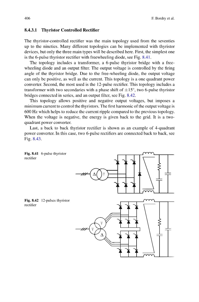
devices, but only the three main types will be described here. First, the simplest one
is the 6-pulse thyristor rectifier with freewheeling diode, see Fig. 8.41.
The topology includes a transformer, a 6-pulse thyristor bridge with a freewheeling diode and an output filter. The output voltage is controlled by the firing
angle of the thyristor bridge. Due to the free-wheeling diode, the output voltage
can only be positive, as well as the current. This topology is a one quadrant power
converter. Second, the most used is the 12-pulse rectifier. This topology includes a
transformer with two secondaries with a phase shift of ±15 ◦ , two 6-pulse thyristor
bridges connected in series, and an output filter, see Fig. 8.42.
This topology allows positive and negative output voltages, but imposes a
minimum current to control the thyristors. The first harmonic of the output voltage is
600 Hz which helps to reduce the current ripple compared to the previous topology.
When the voltage is negative, the energy is given back to the grid. It is a twoquadrant power converter.
Last, a back to back thyristor rectifier is shown as an example of 4-quadrant
power converter. In this case, two 6-pulse rectifiers are connected back to back, see
Fig. 8.43.
Fig. 8.41 6-pulse thyristor
rectifier
Y
Δ
Fig. 8.42 12-pulses thyristor
rectifier
V
V
Δ
F. Bordry et al.
8.4.3.1 Thyristor Controlled Rectifier
The thyristor-controlled rectifier was the main topology used from the seventies
up to the nineties. Many different topologies can be implemented with thyristor
devices, but only the three main types will be described here. First, the simplest one
is the 6-pulse thyristor rectifier with freewheeling diode, see Fig. 8.41.
The topology includes a transformer, a 6-pulse thyristor bridge with a freewheeling diode and an output filter. The output voltage is controlled by the firing
angle of the thyristor bridge. Due to the free-wheeling diode, the output voltage
can only be positive, as well as the current. This topology is a one quadrant power
converter. Second, the most used is the 12-pulse rectifier. This topology includes a
transformer with two secondaries with a phase shift of ±15 ◦ , two 6-pulse thyristor
bridges connected in series, and an output filter, see Fig. 8.42.
This topology allows positive and negative output voltages, but imposes a
minimum current to control the thyristors. The first harmonic of the output voltage is
600 Hz which helps to reduce the current ripple compared to the previous topology.
When the voltage is negative, the energy is given back to the grid. It is a twoquadrant power converter.
Last, a back to back thyristor rectifier is shown as an example of 4-quadrant
power converter. In this case, two 6-pulse rectifiers are connected back to back, see
Fig. 8.43.
Fig. 8.41 6-pulse thyristor
rectifier
Y
Δ
Fig. 8.42 12-pulses thyristor
rectifier
V
V
Δ