

8 Accelerator Engineering and Technology: Accelerator Technology
405
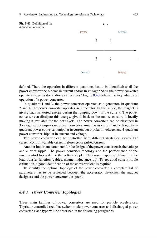
Fig. 8.40 Definition of the
4-quadrant operation
1
4
3
2
I
V
Receptor
Receptor
Generator
Generator
defined. Then, the operation in different quadrants has to be identified: shall the
power converter be bipolar in current and/or in voltage? Shall the power converter
operate as a generator and/or as a receptor? Figure 8.40 defines the 4-quadrants of
operation of a power converter.
In quadrant 1 and 3, the power converter operates as a generator. In quadrant
2 and 4, the power converter operates as a receptor. In this mode, the magnet is
giving back its stored energy during the ramping down of the current. The power
converter can dissipate this energy, give it back to the mains, or store it locally
making it available for the next cycle. The power converters can be classified in
3 categories: one-quadrant power converter; unipolar in current and voltage, twoquadrant power converter; unipolar in current but bipolar in voltage, and 4-quadrant
power converter; bipolar in current and voltage.
The power converter can be controlled with different strategies: steady DC
current control, variable current reference, or pulsed current.
Another important parameter for the design of the power converters is the voltage
and current ripple. The power converter topology and the performance of the
inner control loops define the voltage ripple. The current ripple is defined by the
load transfer function (cables, magnet inductance . . . ). To get good current ripple
estimation, a good identification of the converter load is required.
To identify the optimal topology of the power converter, a complete list of
parameters has to be reviewed between the accelerator physicists, the magnet
designers and the power converter designers.
8.4.3 Power Converter Topologies
Three main families of power converters are used for particle accelerators:
Thyristor-controlled rectifier, switch-mode power converter and discharged power
converter. Each type will be described in the following paragraphs.
405
Fig. 8.40 Definition of the
4-quadrant operation
1
4
3
2
I
V
Receptor
Receptor
Generator
Generator
defined. Then, the operation in different quadrants has to be identified: shall the
power converter be bipolar in current and/or in voltage? Shall the power converter
operate as a generator and/or as a receptor? Figure 8.40 defines the 4-quadrants of
operation of a power converter.
In quadrant 1 and 3, the power converter operates as a generator. In quadrant
2 and 4, the power converter operates as a receptor. In this mode, the magnet is
giving back its stored energy during the ramping down of the current. The power
converter can dissipate this energy, give it back to the mains, or store it locally
making it available for the next cycle. The power converters can be classified in
3 categories: one-quadrant power converter; unipolar in current and voltage, twoquadrant power converter; unipolar in current but bipolar in voltage, and 4-quadrant
power converter; bipolar in current and voltage.
The power converter can be controlled with different strategies: steady DC
current control, variable current reference, or pulsed current.
Another important parameter for the design of the power converters is the voltage
and current ripple. The power converter topology and the performance of the
inner control loops define the voltage ripple. The current ripple is defined by the
load transfer function (cables, magnet inductance . . . ). To get good current ripple
estimation, a good identification of the converter load is required.
To identify the optimal topology of the power converter, a complete list of
parameters has to be reviewed between the accelerator physicists, the magnet
designers and the power converter designers.
8.4.3 Power Converter Topologies
Three main families of power converters are used for particle accelerators:
Thyristor-controlled rectifier, switch-mode power converter and discharged power
converter. Each type will be described in the following paragraphs.