

8 Accelerator Engineering and Technology: Accelerator Technology
379
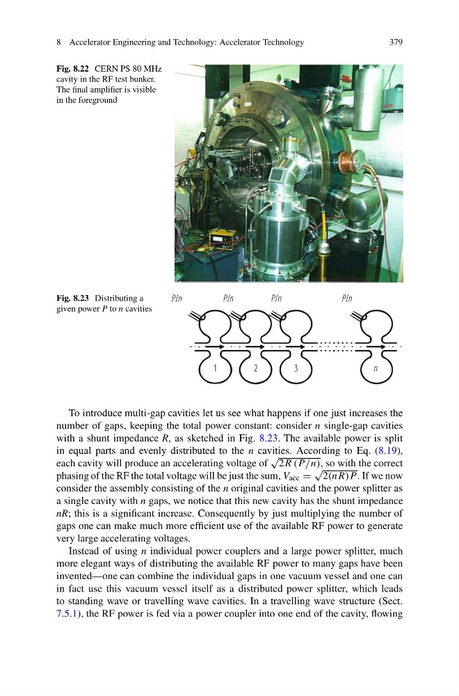
Fig. 8.22 CERN PS 80 MHz
cavity in the RF test bunker.
The final amplifier is visible
in the foreground
Fig. 8.23 Distributing a
given power P to n cavities
To introduce multi-gap cavities let us see what happens if one just increases the
number of gaps, keeping the total power constant: consider n single-gap cavities
with a shunt impedance R, as sketched in Fig. 8.23. The available power is split
in equal parts and evenly distributed to the n cavities. According to Eq. (8.19),
each cavity will produce an accelerating voltage of
√
2R (P /n), so with the correct
phasing of the RF the total voltage will be just the sum, V acc =
√
2(nR)P . If we now
consider the assembly consisting of the n original cavities and the power splitter as
a single cavity with n gaps, we notice that this new cavity has the shunt impedance
nR; this is a significant increase. Consequently by just multiplying the number of
gaps one can make much more efficient use of the available RF power to generate
very large accelerating voltages.
Instead of using n individual power couplers and a large power splitter, much
more elegant ways of distributing the available RF power to many gaps have been
invented—one can combine the individual gaps in one vacuum vessel and one can
in fact use this vacuum vessel itself as a distributed power splitter, which leads
to standing wave or travelling wave cavities. In a travelling wave structure (Sect.
7.5.1), the RF power is fed via a power coupler into one end of the cavity, flowing
379
Fig. 8.22 CERN PS 80 MHz
cavity in the RF test bunker.
The final amplifier is visible
in the foreground
Fig. 8.23 Distributing a
given power P to n cavities
To introduce multi-gap cavities let us see what happens if one just increases the
number of gaps, keeping the total power constant: consider n single-gap cavities
with a shunt impedance R, as sketched in Fig. 8.23. The available power is split
in equal parts and evenly distributed to the n cavities. According to Eq. (8.19),
each cavity will produce an accelerating voltage of
√
2R (P /n), so with the correct
phasing of the RF the total voltage will be just the sum, V acc =
√
2(nR)P . If we now
consider the assembly consisting of the n original cavities and the power splitter as
a single cavity with n gaps, we notice that this new cavity has the shunt impedance
nR; this is a significant increase. Consequently by just multiplying the number of
gaps one can make much more efficient use of the available RF power to generate
very large accelerating voltages.
Instead of using n individual power couplers and a large power splitter, much
more elegant ways of distributing the available RF power to many gaps have been
invented—one can combine the individual gaps in one vacuum vessel and one can
in fact use this vacuum vessel itself as a distributed power splitter, which leads
to standing wave or travelling wave cavities. In a travelling wave structure (Sect.
7.5.1), the RF power is fed via a power coupler into one end of the cavity, flowing