

378
F. Bordry et al.
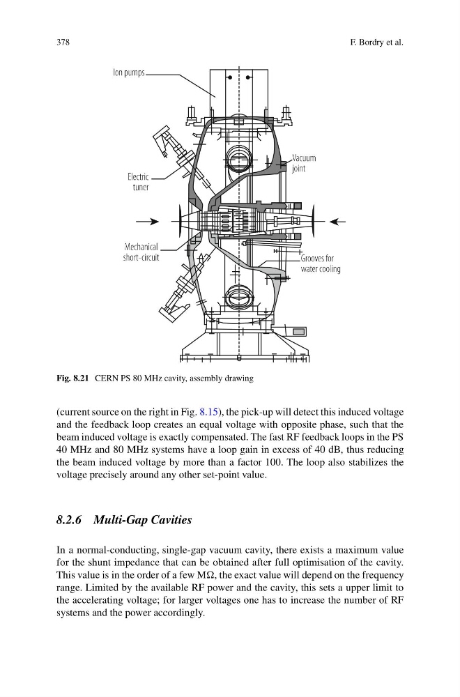
Fig. 8.21 CERN PS 80 MHz cavity, assembly drawing
(current source on the right in Fig. 8.15), the pick-up will detect this induced voltage
and the feedback loop creates an equal voltage with opposite phase, such that the
beam induced voltage is exactly compensated. The fast RF feedback loops in the PS
40 MHz and 80 MHz systems have a loop gain in excess of 40 dB, thus reducing
the beam induced voltage by more than a factor 100. The loop also stabilizes the
voltage precisely around any other set-point value.
8.2.6 Multi-Gap Cavities
In a normal-conducting, single-gap vacuum cavity, there exists a maximum value
for the shunt impedance that can be obtained after full optimisation of the cavity.
This value is in the order of a few M, the exact value will depend on the frequency
range. Limited by the available RF power and the cavity, this sets a upper limit to
the accelerating voltage; for larger voltages one has to increase the number of RF
systems and the power accordingly.
F. Bordry et al.
Fig. 8.21 CERN PS 80 MHz cavity, assembly drawing
(current source on the right in Fig. 8.15), the pick-up will detect this induced voltage
and the feedback loop creates an equal voltage with opposite phase, such that the
beam induced voltage is exactly compensated. The fast RF feedback loops in the PS
40 MHz and 80 MHz systems have a loop gain in excess of 40 dB, thus reducing
the beam induced voltage by more than a factor 100. The loop also stabilizes the
voltage precisely around any other set-point value.
8.2.6 Multi-Gap Cavities
In a normal-conducting, single-gap vacuum cavity, there exists a maximum value
for the shunt impedance that can be obtained after full optimisation of the cavity.
This value is in the order of a few M, the exact value will depend on the frequency
range. Limited by the available RF power and the cavity, this sets a upper limit to
the accelerating voltage; for larger voltages one has to increase the number of RF
systems and the power accordingly.