

372
F. Bordry et al.
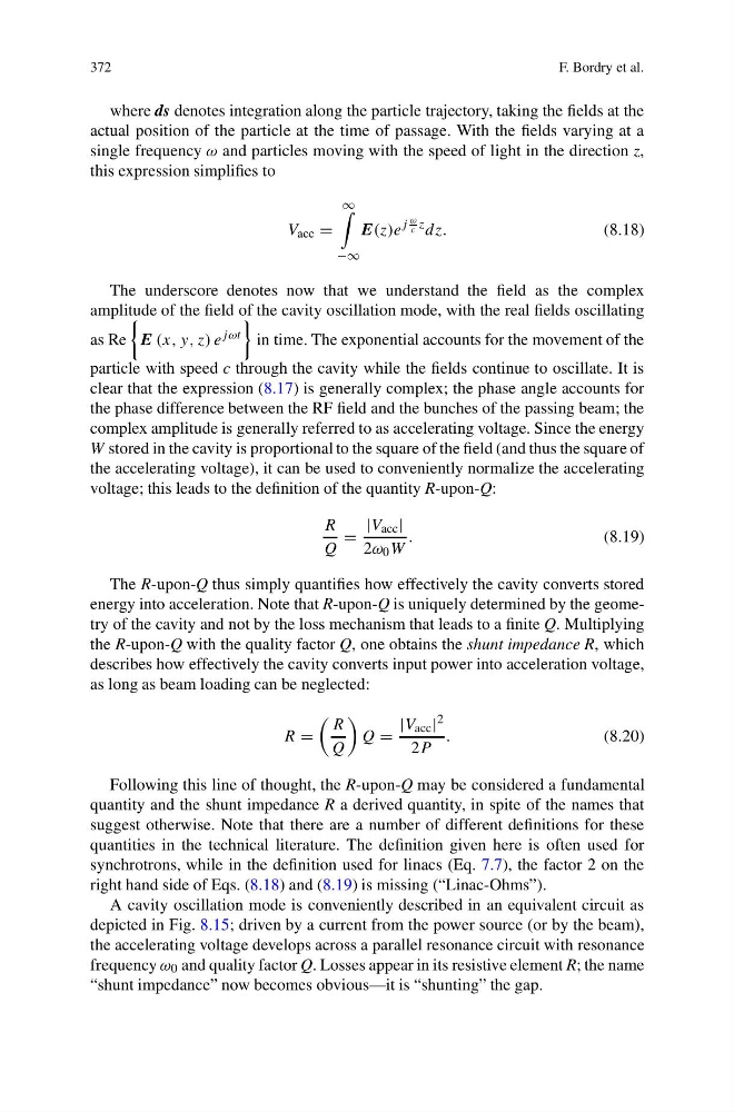
where ds denotes integration along the particle trajectory, taking the fields at the
actual position of the particle at the time of passage. With the fields varying at a
single frequency ω and particles moving with the speed of light in the direction z,
this expression simplifies to
V acc =
∞
−∞
E(z)e
j
ω
c z dz.
(8.18)
The underscore denotes now that we understand the field as the complex
amplitude of the field of the cavity oscillation mode, with the real fields oscillating
as Re
E (x, y, z) e jωt
in time. The exponential accounts for the movement of the
particle with speed c through the cavity while the fields continue to oscillate. It is
clear that the expression (8.17) is generally complex; the phase angle accounts for
the phase difference between the RF field and the bunches of the passing beam; the
complex amplitude is generally referred to as accelerating voltage. Since the energy
W stored in the cavity is proportional to the square of the field (and thus the square of
the accelerating voltage), it can be used to conveniently normalize the accelerating
voltage; this leads to the definition of the quantity R-upon-Q:
R
Q
=
|V acc |
2ω 0 W
.
(8.19)
The R-upon-Q thus simply quantifies how effectively the cavity converts stored
energy into acceleration. Note that R-upon-Q is uniquely determined by the geometry of the cavity and not by the loss mechanism that leads to a finite Q. Multiplying
the R-upon-Q with the quality factor Q, one obtains the shunt impedance R, which
describes how effectively the cavity converts input power into acceleration voltage,
as long as beam loading can be neglected:
R =
R
Q
Q =
|V acc | 2
2P
.
(8.20)
Following this line of thought, the R-upon-Q may be considered a fundamental
quantity and the shunt impedance R a derived quantity, in spite of the names that
suggest otherwise. Note that there are a number of different definitions for these
quantities in the technical literature. The definition given here is often used for
synchrotrons, while in the definition used for linacs (Eq. 7.7), the factor 2 on the
right hand side of Eqs. (8.18) and (8.19) is missing (“Linac-Ohms”).
A cavity oscillation mode is conveniently described in an equivalent circuit as
depicted in Fig. 8.15; driven by a current from the power source (or by the beam),
the accelerating voltage develops across a parallel resonance circuit with resonance
frequency ω 0 and quality factor Q. Losses appear in its resistive element R; the name
“shunt impedance” now becomes obvious—it is “shunting” the gap.
F. Bordry et al.
where ds denotes integration along the particle trajectory, taking the fields at the
actual position of the particle at the time of passage. With the fields varying at a
single frequency ω and particles moving with the speed of light in the direction z,
this expression simplifies to
V acc =
∞
−∞
E(z)e
j
ω
c z dz.
(8.18)
The underscore denotes now that we understand the field as the complex
amplitude of the field of the cavity oscillation mode, with the real fields oscillating
as Re
E (x, y, z) e jωt
in time. The exponential accounts for the movement of the
particle with speed c through the cavity while the fields continue to oscillate. It is
clear that the expression (8.17) is generally complex; the phase angle accounts for
the phase difference between the RF field and the bunches of the passing beam; the
complex amplitude is generally referred to as accelerating voltage. Since the energy
W stored in the cavity is proportional to the square of the field (and thus the square of
the accelerating voltage), it can be used to conveniently normalize the accelerating
voltage; this leads to the definition of the quantity R-upon-Q:
R
Q
=
|V acc |
2ω 0 W
.
(8.19)
The R-upon-Q thus simply quantifies how effectively the cavity converts stored
energy into acceleration. Note that R-upon-Q is uniquely determined by the geometry of the cavity and not by the loss mechanism that leads to a finite Q. Multiplying
the R-upon-Q with the quality factor Q, one obtains the shunt impedance R, which
describes how effectively the cavity converts input power into acceleration voltage,
as long as beam loading can be neglected:
R =
R
Q
Q =
|V acc | 2
2P
.
(8.20)
Following this line of thought, the R-upon-Q may be considered a fundamental
quantity and the shunt impedance R a derived quantity, in spite of the names that
suggest otherwise. Note that there are a number of different definitions for these
quantities in the technical literature. The definition given here is often used for
synchrotrons, while in the definition used for linacs (Eq. 7.7), the factor 2 on the
right hand side of Eqs. (8.18) and (8.19) is missing (“Linac-Ohms”).
A cavity oscillation mode is conveniently described in an equivalent circuit as
depicted in Fig. 8.15; driven by a current from the power source (or by the beam),
the accelerating voltage develops across a parallel resonance circuit with resonance
frequency ω 0 and quality factor Q. Losses appear in its resistive element R; the name
“shunt impedance” now becomes obvious—it is “shunting” the gap.