

8 Accelerator Engineering and Technology: Accelerator Technology
373
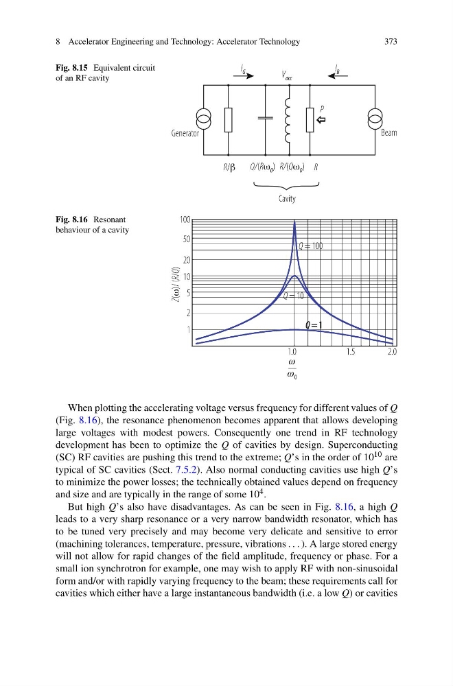
Fig. 8.15 Equivalent circuit
of an RF cavity
Fig. 8.16 Resonant
behaviour of a cavity
When plotting the accelerating voltage versus frequency for different values of Q
(Fig. 8.16), the resonance phenomenon becomes apparent that allows developing
large voltages with modest powers. Consequently one trend in RF technology
development has been to optimize the Q of cavities by design. Superconducting
(SC) RF cavities are pushing this trend to the extreme; Q’s in the order of 10 10 are
typical of SC cavities (Sect. 7.5.2). Also normal conducting cavities use high Q’s
to minimize the power losses; the technically obtained values depend on frequency
and size and are typically in the range of some 10 4 .
But high Q’s also have disadvantages. As can be seen in Fig. 8.16, a high Q
leads to a very sharp resonance or a very narrow bandwidth resonator, which has
to be tuned very precisely and may become very delicate and sensitive to error
(machining tolerances, temperature, pressure, vibrations . . . ). A large stored energy
will not allow for rapid changes of the field amplitude, frequency or phase. For a
small ion synchrotron for example, one may wish to apply RF with non-sinusoidal
form and/or with rapidly varying frequency to the beam; these requirements call for
cavities which either have a large instantaneous bandwidth (i.e. a low Q) or cavities
373
Fig. 8.15 Equivalent circuit
of an RF cavity
Fig. 8.16 Resonant
behaviour of a cavity
When plotting the accelerating voltage versus frequency for different values of Q
(Fig. 8.16), the resonance phenomenon becomes apparent that allows developing
large voltages with modest powers. Consequently one trend in RF technology
development has been to optimize the Q of cavities by design. Superconducting
(SC) RF cavities are pushing this trend to the extreme; Q’s in the order of 10 10 are
typical of SC cavities (Sect. 7.5.2). Also normal conducting cavities use high Q’s
to minimize the power losses; the technically obtained values depend on frequency
and size and are typically in the range of some 10 4 .
But high Q’s also have disadvantages. As can be seen in Fig. 8.16, a high Q
leads to a very sharp resonance or a very narrow bandwidth resonator, which has
to be tuned very precisely and may become very delicate and sensitive to error
(machining tolerances, temperature, pressure, vibrations . . . ). A large stored energy
will not allow for rapid changes of the field amplitude, frequency or phase. For a
small ion synchrotron for example, one may wish to apply RF with non-sinusoidal
form and/or with rapidly varying frequency to the beam; these requirements call for
cavities which either have a large instantaneous bandwidth (i.e. a low Q) or cavities