

8 Accelerator Engineering and Technology: Accelerator Technology
371
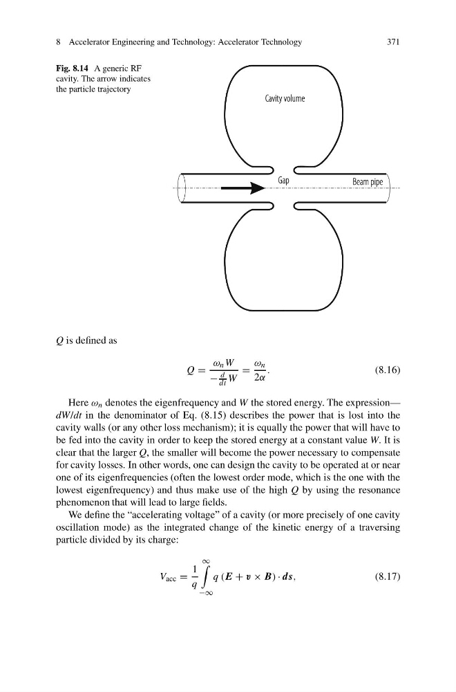
Fig. 8.14 A generic RF
cavity. The arrow indicates
the particle trajectory
Q is defined as
Q =
ω n W
−
d
dt W
=
ω n
2α
.
(8.16)
Here ω n denotes the eigenfrequency and W the stored energy. The expression—
dW/dt in the denominator of Eq. (8.15) describes the power that is lost into the
cavity walls (or any other loss mechanism); it is equally the power that will have to
be fed into the cavity in order to keep the stored energy at a constant value W. It is
clear that the larger Q, the smaller will become the power necessary to compensate
for cavity losses. In other words, one can design the cavity to be operated at or near
one of its eigenfrequencies (often the lowest order mode, which is the one with the
lowest eigenfrequency) and thus make use of the high Q by using the resonance
phenomenon that will lead to large fields.
We define the “accelerating voltage” of a cavity (or more precisely of one cavity
oscillation mode) as the integrated change of the kinetic energy of a traversing
particle divided by its charge:
V acc =
1
q
∞
−∞
q (E + v × B) · ds,
(8.17)
371
Fig. 8.14 A generic RF
cavity. The arrow indicates
the particle trajectory
Q is defined as
Q =
ω n W
−
d
dt W
=
ω n
2α
.
(8.16)
Here ω n denotes the eigenfrequency and W the stored energy. The expression—
dW/dt in the denominator of Eq. (8.15) describes the power that is lost into the
cavity walls (or any other loss mechanism); it is equally the power that will have to
be fed into the cavity in order to keep the stored energy at a constant value W. It is
clear that the larger Q, the smaller will become the power necessary to compensate
for cavity losses. In other words, one can design the cavity to be operated at or near
one of its eigenfrequencies (often the lowest order mode, which is the one with the
lowest eigenfrequency) and thus make use of the high Q by using the resonance
phenomenon that will lead to large fields.
We define the “accelerating voltage” of a cavity (or more precisely of one cavity
oscillation mode) as the integrated change of the kinetic energy of a traversing
particle divided by its charge:
V acc =
1
q
∞
−∞
q (E + v × B) · ds,
(8.17)