

358
F. Bordry et al.
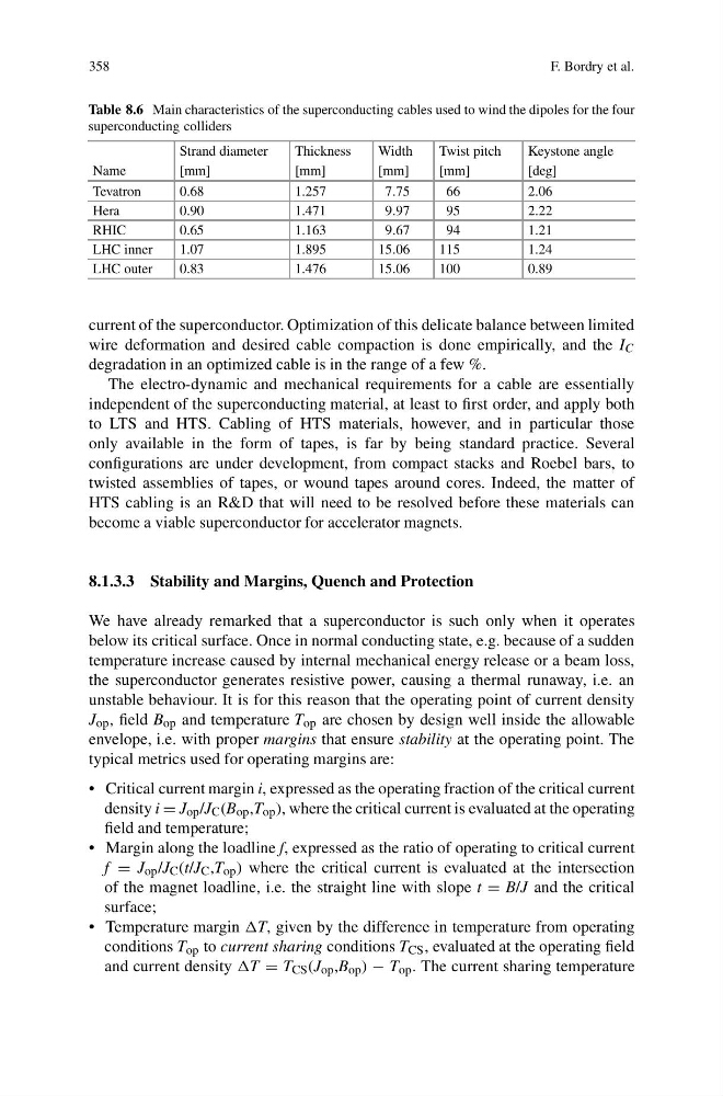
Table 8.6 Main characteristics of the superconducting cables used to wind the dipoles for the four
superconducting colliders
Strand diameter
Thickness
Width
Twist pitch
Keystone angle
Name
[mm]
[mm]
[mm]
[mm]
[deg]
Tevatron
0.68
1.257
7.75
66
2.06
Hera
0.90
1.471
9.97
95
2.22
RHIC
0.65
1.163
9.67
94
1.21
LHC inner
1.07
1.895
15.06
115
1.24
LHC outer
0.83
1.476
15.06
100
0.89
current of the superconductor. Optimization of this delicate balance between limited
wire deformation and desired cable compaction is done empirically, and the I C
degradation in an optimized cable is in the range of a few %.
The electro-dynamic and mechanical requirements for a cable are essentially
independent of the superconducting material, at least to first order, and apply both
to LTS and HTS. Cabling of HTS materials, however, and in particular those
only available in the form of tapes, is far by being standard practice. Several
configurations are under development, from compact stacks and Roebel bars, to
twisted assemblies of tapes, or wound tapes around cores. Indeed, the matter of
HTS cabling is an R&D that will need to be resolved before these materials can
become a viable superconductor for accelerator magnets.
8.1.3.3 Stability and Margins, Quench and Protection
We have already remarked that a superconductor is such only when it operates
below its critical surface. Once in normal conducting state, e.g. because of a sudden
temperature increase caused by internal mechanical energy release or a beam loss,
the superconductor generates resistive power, causing a thermal runaway, i.e. an
unstable behaviour. It is for this reason that the operating point of current density
J op , field B op and temperature T op are chosen by design well inside the allowable
envelope, i.e. with proper margins that ensure stability at the operating point. The
typical metrics used for operating margins are:
• Critical current margin i, expressed as the operating fraction of the critical current
density i = J op /J C (B op ,T op ), where the critical current is evaluated at the operating
field and temperature;
• Margin along the loadline f, expressed as the ratio of operating to critical current
f = J op /J C (t/J C ,T op ) where the critical current is evaluated at the intersection
of the magnet loadline, i.e. the straight line with slope t = B/J and the critical
surface;
• Temperature margin given by the difference in temperature from operating
conditions T op to current sharing conditions T CS , evaluated at the operating field
and current density = T CS (J op ,B op ) − T op . The current sharing temperature
F. Bordry et al.
Table 8.6 Main characteristics of the superconducting cables used to wind the dipoles for the four
superconducting colliders
Strand diameter
Thickness
Width
Twist pitch
Keystone angle
Name
[mm]
[mm]
[mm]
[mm]
[deg]
Tevatron
0.68
1.257
7.75
66
2.06
Hera
0.90
1.471
9.97
95
2.22
RHIC
0.65
1.163
9.67
94
1.21
LHC inner
1.07
1.895
15.06
115
1.24
LHC outer
0.83
1.476
15.06
100
0.89
current of the superconductor. Optimization of this delicate balance between limited
wire deformation and desired cable compaction is done empirically, and the I C
degradation in an optimized cable is in the range of a few %.
The electro-dynamic and mechanical requirements for a cable are essentially
independent of the superconducting material, at least to first order, and apply both
to LTS and HTS. Cabling of HTS materials, however, and in particular those
only available in the form of tapes, is far by being standard practice. Several
configurations are under development, from compact stacks and Roebel bars, to
twisted assemblies of tapes, or wound tapes around cores. Indeed, the matter of
HTS cabling is an R&D that will need to be resolved before these materials can
become a viable superconductor for accelerator magnets.
8.1.3.3 Stability and Margins, Quench and Protection
We have already remarked that a superconductor is such only when it operates
below its critical surface. Once in normal conducting state, e.g. because of a sudden
temperature increase caused by internal mechanical energy release or a beam loss,
the superconductor generates resistive power, causing a thermal runaway, i.e. an
unstable behaviour. It is for this reason that the operating point of current density
J op , field B op and temperature T op are chosen by design well inside the allowable
envelope, i.e. with proper margins that ensure stability at the operating point. The
typical metrics used for operating margins are:
• Critical current margin i, expressed as the operating fraction of the critical current
density i = J op /J C (B op ,T op ), where the critical current is evaluated at the operating
field and temperature;
• Margin along the loadline f, expressed as the ratio of operating to critical current
f = J op /J C (t/J C ,T op ) where the critical current is evaluated at the intersection
of the magnet loadline, i.e. the straight line with slope t = B/J and the critical
surface;
• Temperature margin given by the difference in temperature from operating
conditions T op to current sharing conditions T CS , evaluated at the operating field
and current density = T CS (J op ,B op ) − T op . The current sharing temperature